
2014 FRC Build Season Blog
Day 1: Kickoff and Game Analysis
Kickoff Overview
Today kicks off the 2014 FRC Season for Team 254. The mentors and students are equally ecstatic for this year’s challenge, Aerial Assist.
Google Drive PDF of the Game Manual:
https://drive.google.com/file/d/0B_TTQ23_FVkAWjM0cjBsbUw1TkU/edit?usp=sharing
Game Animation:
Team Kickoff
Today a group of students attended the 6:30 to 9:30 local San Jose kickoff at Morris Dailey Auditorium. A few others watched the NASA Live Stream from home. Subsequently, at 10, the team met for the team’s kickoff event and discussed the plan for the coming six-week build season. The team then broke up into groups and discussed strategies in terms of necessary robot qualities, priority tasks, and possible scores. The parents and mentors simultaneously discussed logistics and the build plan in more detail until the student leaders returned to present their ideas to the entire group.
Game Analysis
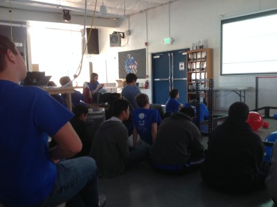
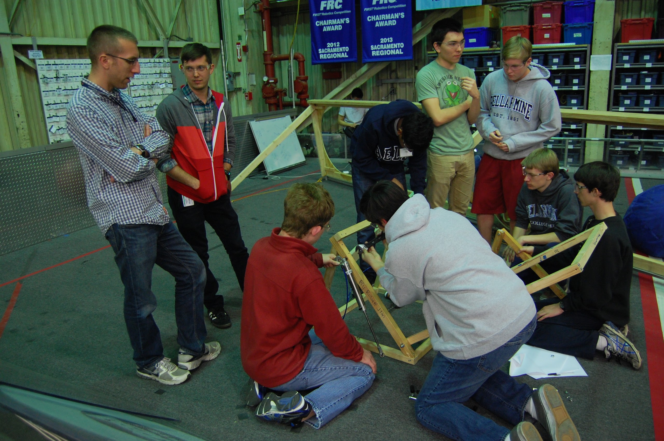
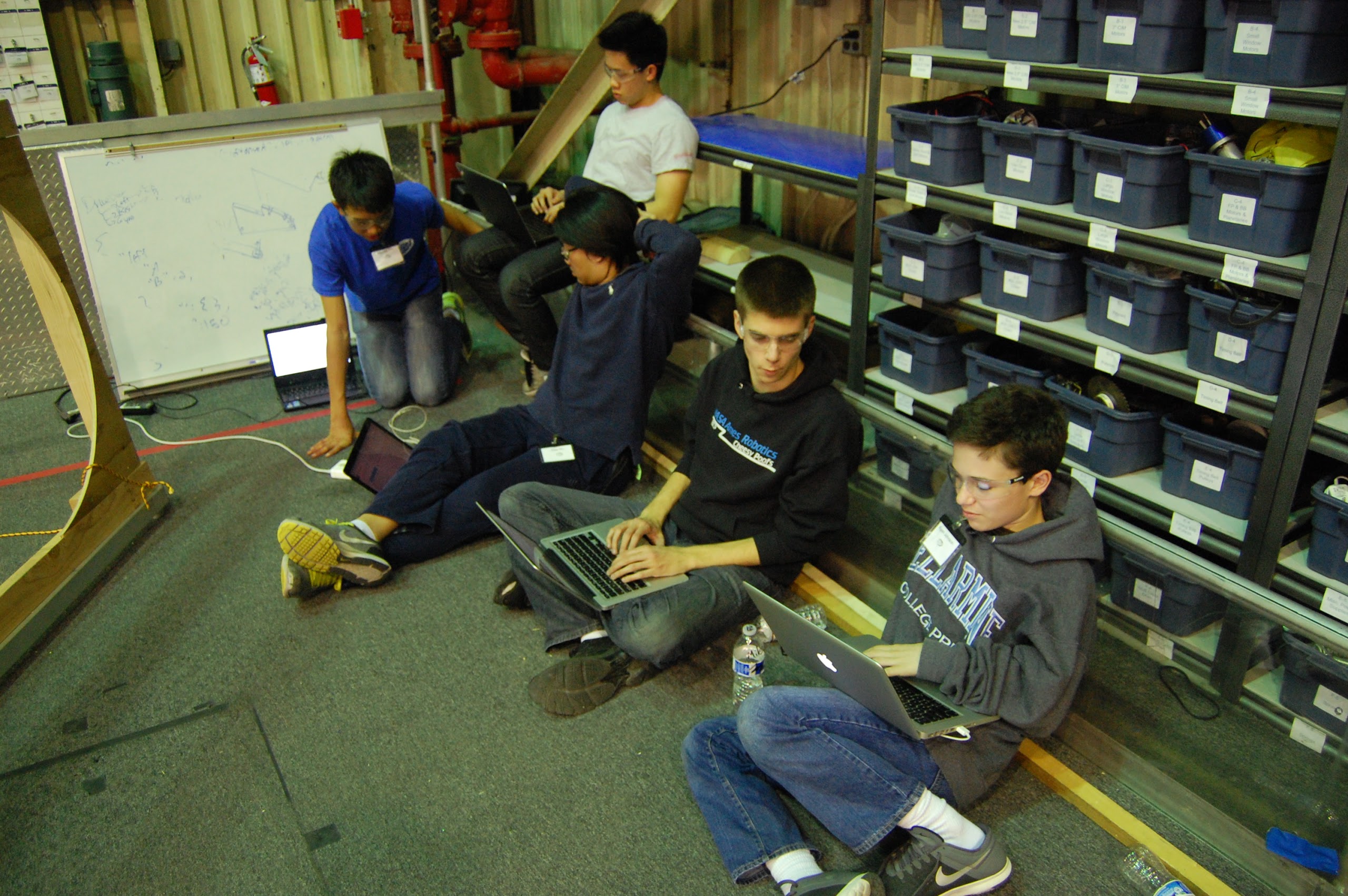
After lunch, about 70 students congregated in the Bellarmine Robotics Lab to examine and better understand the team rules. In particular, they discussed the definitions of assist and possession and clarified the rules for such actions and others on the playing field. For the first two and a half hours, the group went through the relevant sections of the game manual and encouraged group discussion to find possible holes and list them to check with FIRST later. The group noticed some deviations in rules from previous years: the field is two feet narrower at 25 feet, and the match is 30 seconds longer. The autonomous period is five seconds shorter at 10 seconds, and the tele-operated period is 35 seconds longer at 2:20. Andrew Torrance noted the possible issues with battery life with the 25% longer match time. In addition to discussing rules, the team also formulated questions concerning the regulations to ask FIRST:
- Can teams do assists in autonomous?
- Can teams hold balls in autonomous to do an assist later?
- Can a team throw over the truss again to try and get a catch, say, if an alliance earns a successful truss score, but does not successfully catch. Can the alliance try for a second chance? In other words, while the group recognizes that only one truss score counts per cycle, do the truss score and the associated catch score have to be earned on the first attempt?
- Do teams get points (ex. throwing and catching in the end game) immediately, or do the teams only get them once the cycle completes? This is related to the question of assisting in autonomous. Possible answer: Maybe not because autonomous shots are not cycles.
- Teams need clarification on which goalie zone to which the initial position regulations refer. In which goalie zone do teams start if they do not want to start in the white zone? Can human players help in the middle of assists?
- Can human players catch truss scores to make them legal?
- Teams need a better definition of possession for robots in general. For example, for a trough-like robot, is holding the ball as it rolls considered possession? What time period differentiates harmless “deflection” from “possession” of the opponent game object (which earns a severe technical foul penalty)
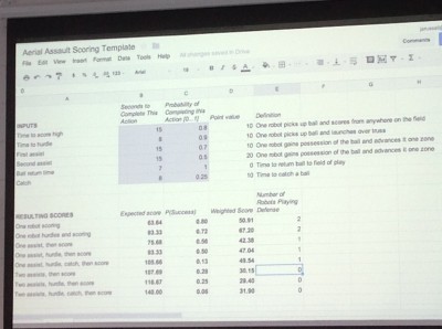
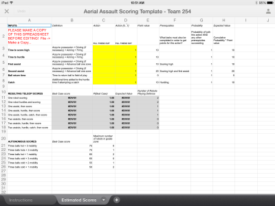
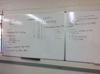
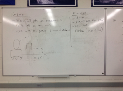
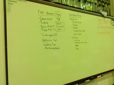
After a short break, the team’s new mentor Jared set up a Google Spreadsheet that evaluated the effectiveness of certain “assist” strategies, with combinations of 1-3 assists, a truss “hurdle,” and the truss “catch.” He took student input for the point values corresponding to each action, the expected time taken for each action, and the probability of the action being carried out successfuly. He then calculated out a rough model of the weighted point values expected from strategies in the tele-operated mode of the match. The group was then able to analyze the efficiency of certain strategies. In the process of discussing strategies, the team also created two other strategy charts and lists (pictured).
Further Analysis and Prototyping
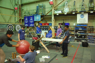
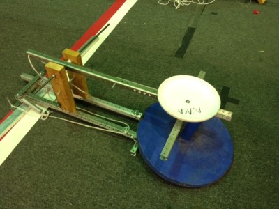
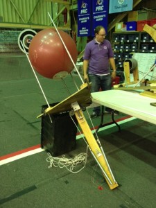
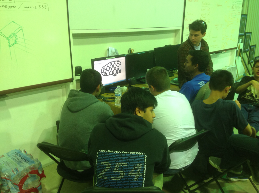
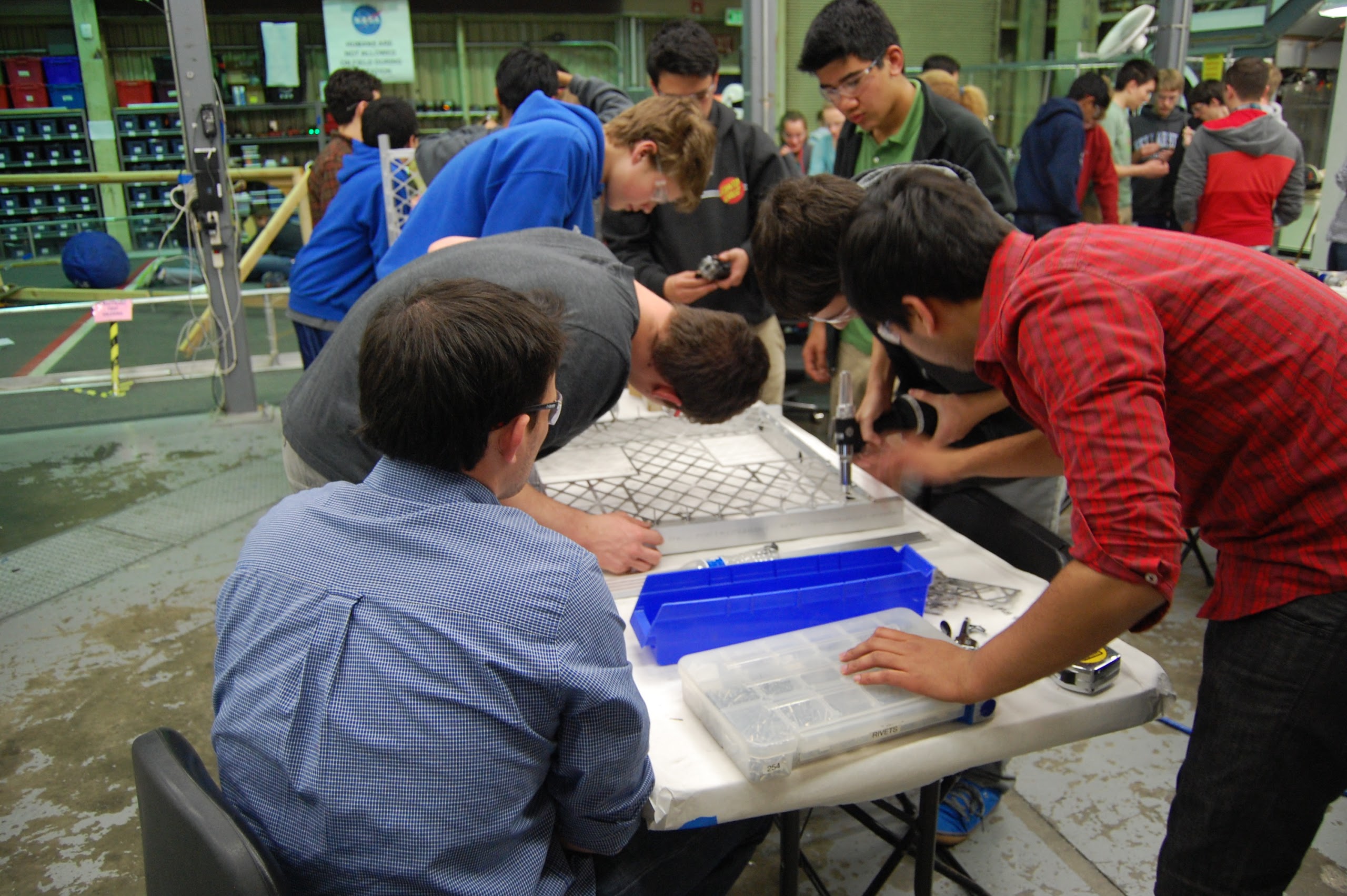
After dinner, approximately 20 students worked with the mentors to list some possible designs and to plan out the next week’s prototyping schedule. The group prioritized the prototyping of possible modules, specifically shooter designs and catching mechanisms, with design input from students and advice from our experienced mentors. They also discussed what field elements were most necessary for prototyping for the next few weeks and listed them as well. Finally, they discussed the mathematics and physics of shooting a 25-inch, compressible, bulky, and irregular projectile into a 3-foot goal. For example, mentors noted that we might as well design a robot to shoot from farther away from the goal, since the shallower angle of entry would give greater allowance for error. Mentor Paul Ventimiglia also determined that giving the large exercise ball some backspin helped in precision, though it also required more energy to apply both linear force and rotational torque.
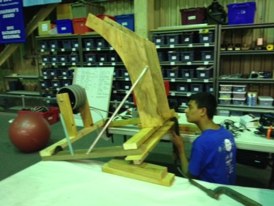
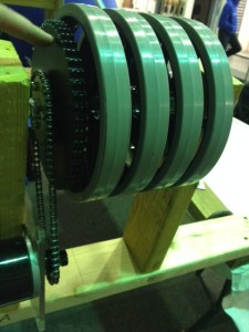
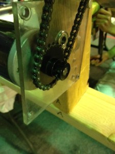
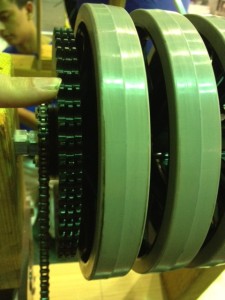
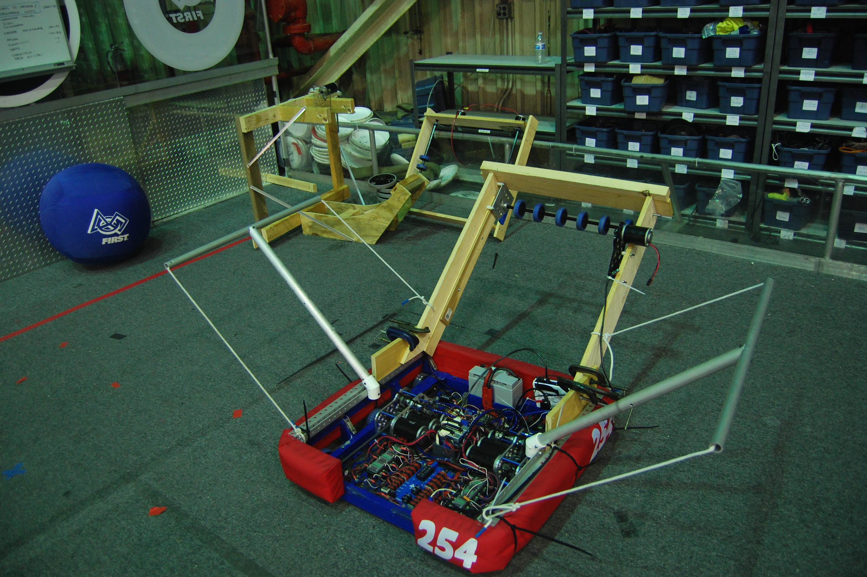
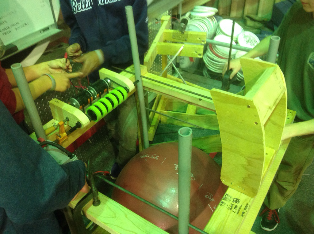
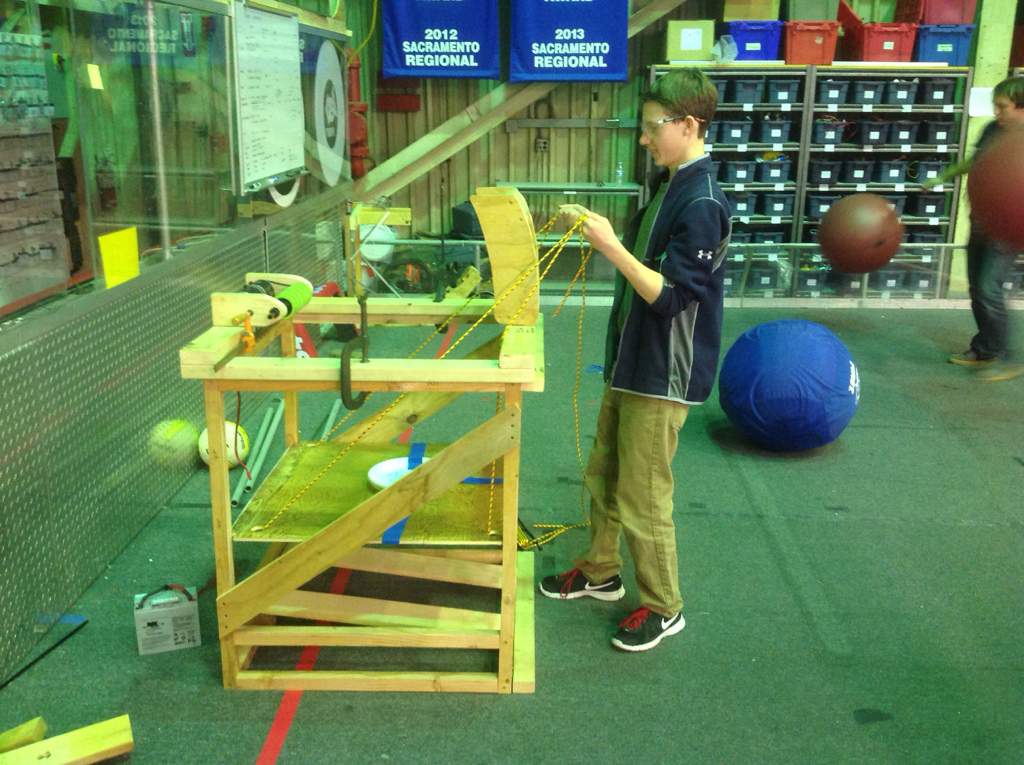
Tonight, we mainly focused on the building a preliminary goal with which to prototype before the field arrives and on prototyping and testing the effectiveness of a flywheel shooter and a slingshot shooter. Paul worked primarily with Godwin Vincent, James Holden, Jeremy Tanlimco, Vidur Maheshwari, Miggy Francisco, and Joncarlo Avila to design, sketch, and begin building a prototype for testing the effectiveness of a flywheel on such a large game object. They determined the best wheels with which to work based on their ability to grip the surface of the unusual game object. The prototype design was finalized and they plan to use four large wheels on the same axle hooked up to curved plywood “rims” to optimize the compression on the ball and somewhat minimize the size of the already bulky prototype. EJ Sabathia and Noah Marcel worked on the slingshot design, taping a 2013 Ultimate Ascent Frisbee to surgical tubing and hooking up the system to an alliance wall. The ball consistently bounced about 1/3 of the way down the court, given about 4 or 5 feet of backward stretch.
Lab closing time: 11:00
Action Items
Translation: Future Work Opportunities for Members
- Help Paul with the Flywheel Shooter design
- Help EJ with Slingshot Shooter design
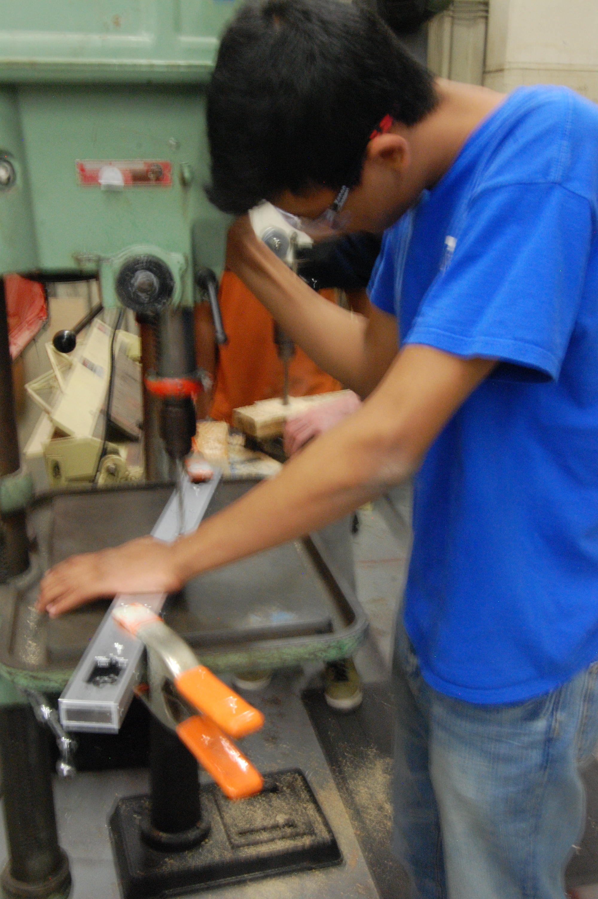
- Help Nick Mercadante machine metal for prototypes
- Ask mentors to begin and lead prototyping projects for other designs
Day 2: Prototyping, Drive base Design, Initial Coding
Prototyping Shooters
Three different teams worked to design, build, and test three different ways to launch the ball. They built a catapult, a linear launcher, and a flywheel shooter.
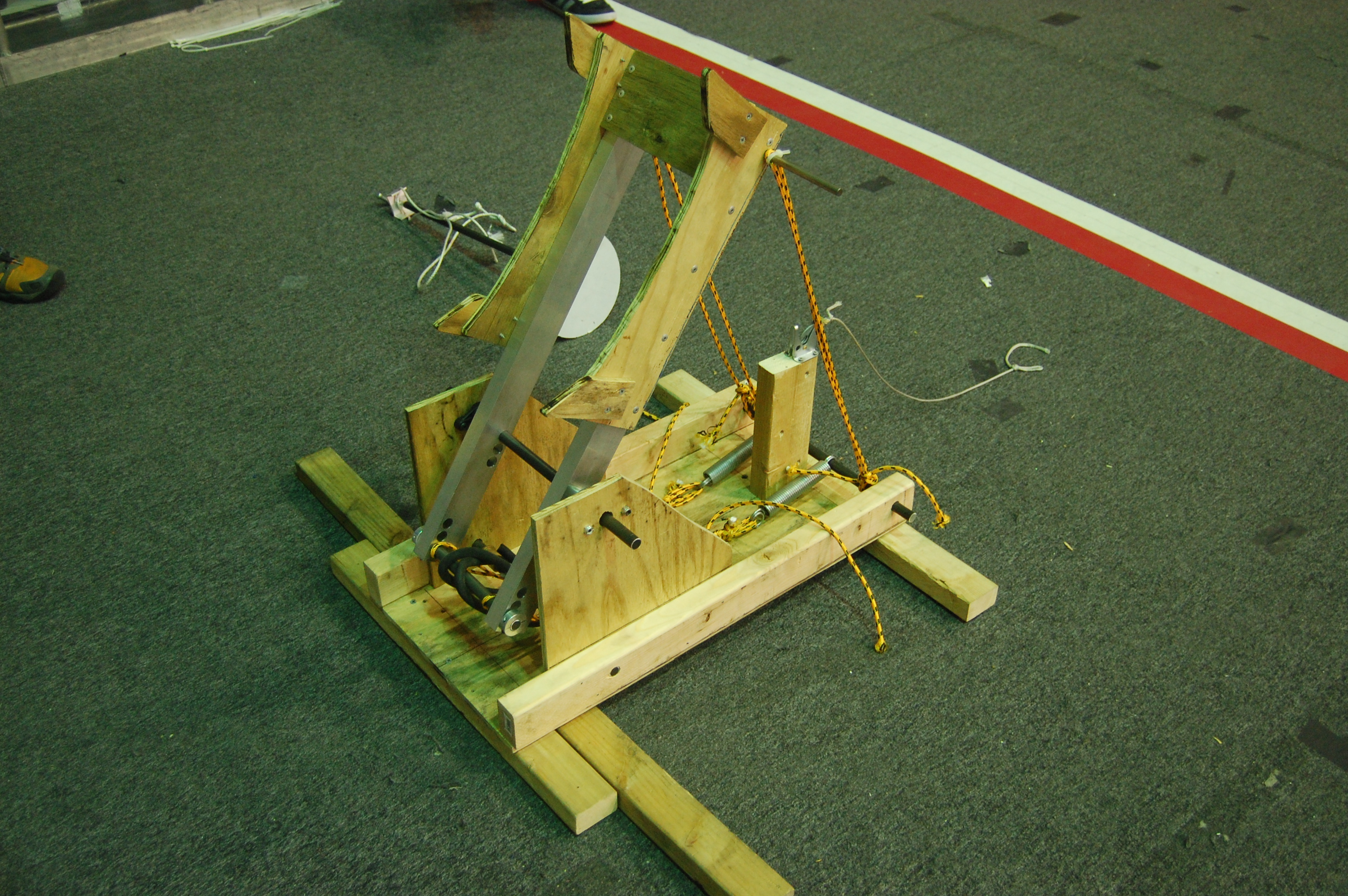
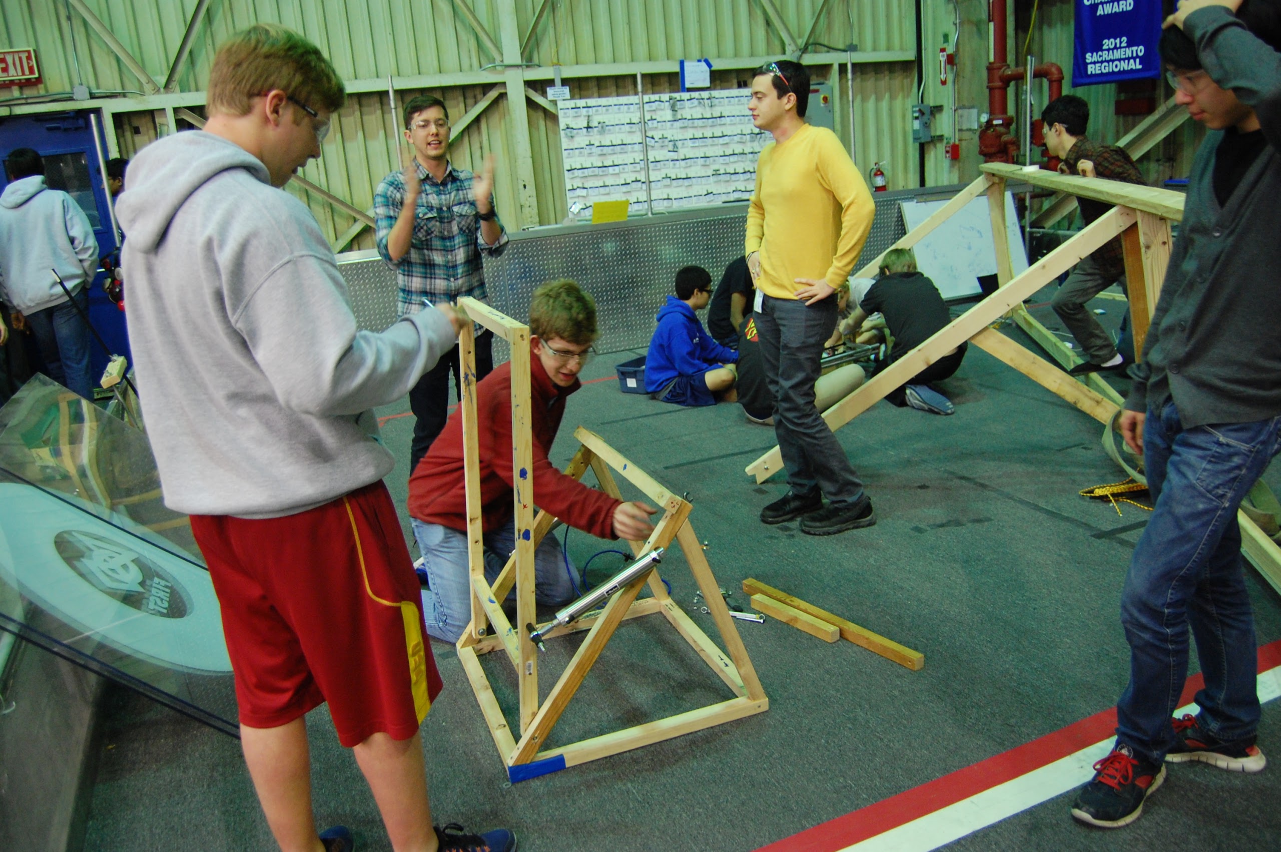
Catapult Launcher
A catapult was designed and built today using a system similar to other catapults we’ve seen for this year and 2008. This quick prototype was not strong enough to launch balls far enough and the team needs to improve the design tomorrow perhaps by making it more stable and utilizing another tension device such as surgical tubing.
Linear “Trident” Launcher
Flywheel Shooter
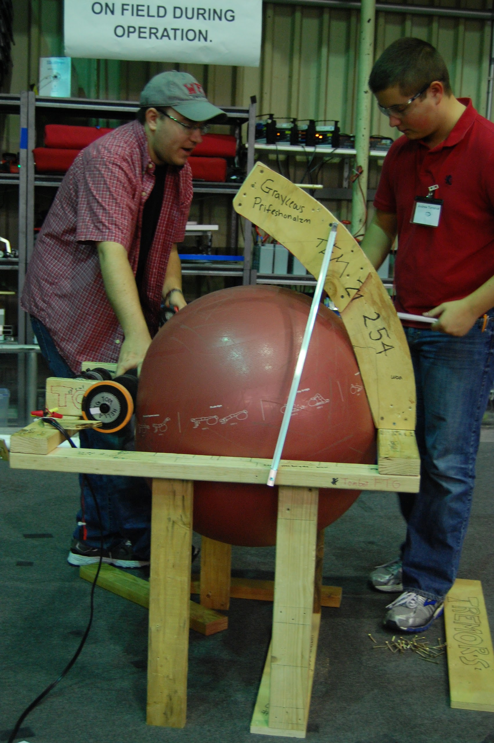
The flywheel shooter was completed today, and students and mentors began testing with it. Of the three shooter prototypes, the flywheel had the best shots and most consistency. Additionally, the team could test the effects of ball pressure on the consistency and accuracy of shots for the first time in the season. By the end of the night the flywheel shooter made about 1/3 to 1/2 of its shots.
Programming
The programmers met today and decided on what they wanted to work on for the next few weeks.
It was decided that we would like to spend time building debugging tools for the robot. The main thing that needs to be built is a way to live graph motor and sensor states, much like the PID tuner we had in 2012.
The programmers also decided to rework how autonomous mode will be executed so that control flow can be used in autonomous rather than just a straight sequence of events.
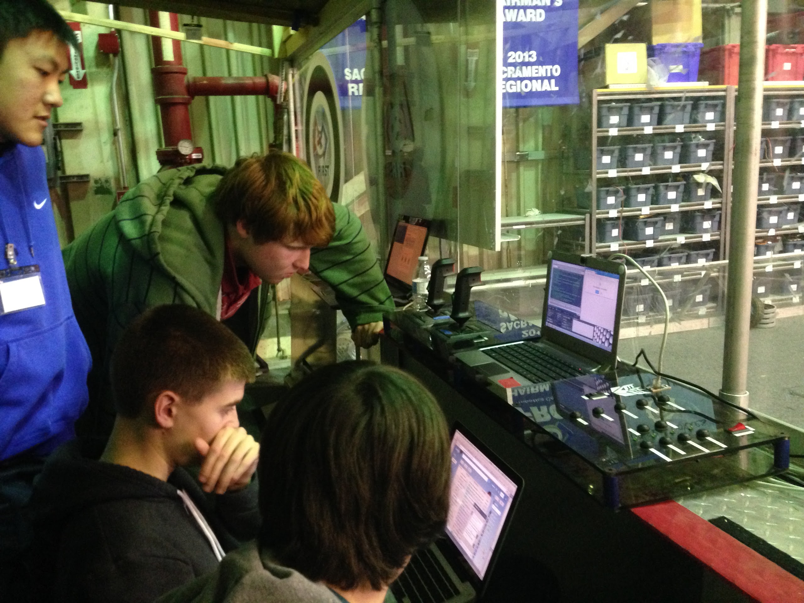
Tom and Stephen started a new Java project for the 2014 robot and got basic CheesyDrive working on the 2013 practice drivebase. This code will use a new subsystem architecture and will use very little code provided by WPI.
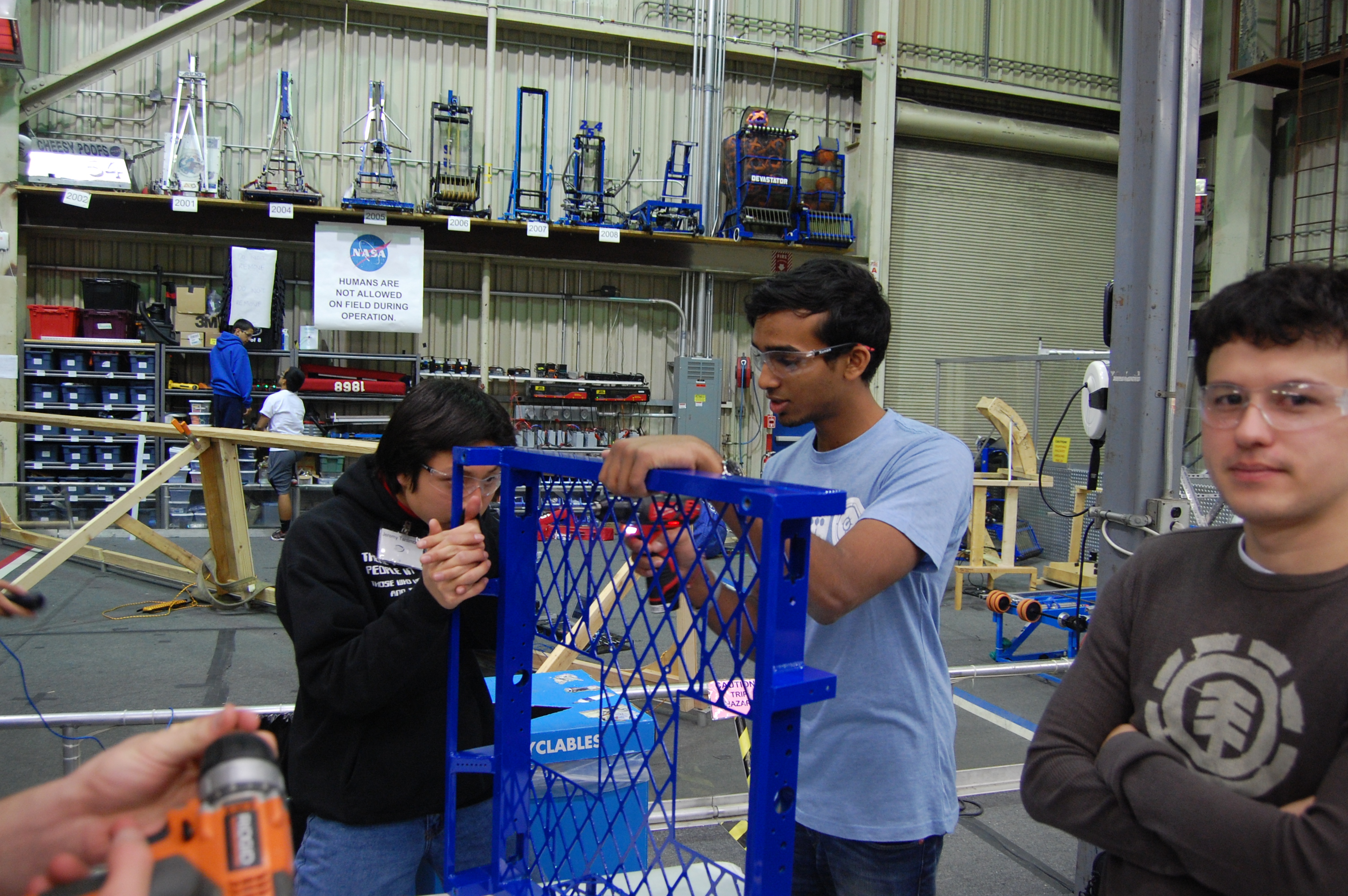
Field Assembly
The team completed the construction and mounting of one full set of high goals. The goals have a ramp designed to return the balls back onto the field so that they do not fall onto drivers. We will use these wooden goals while we wait for the official set to come in from FIRST.
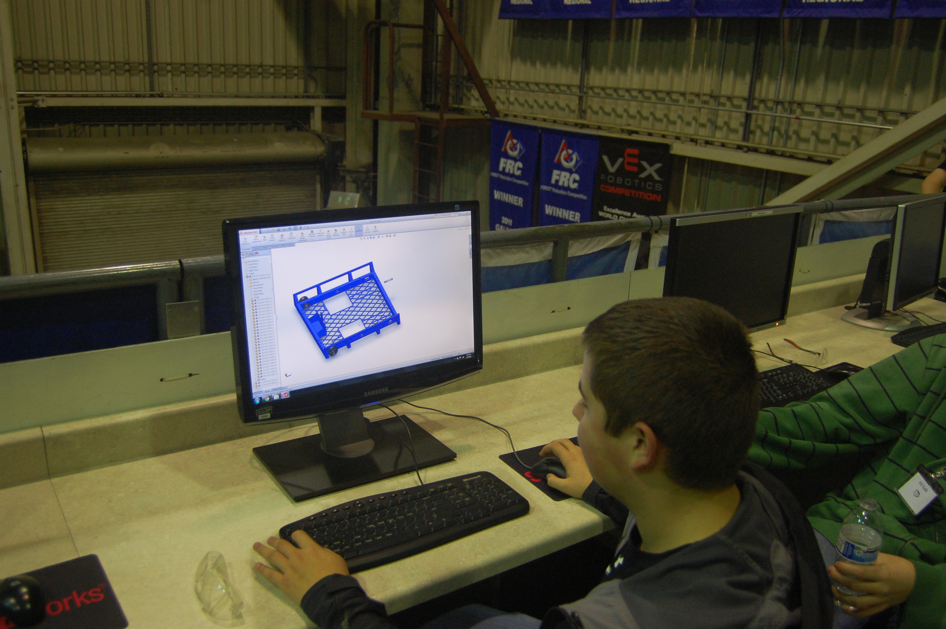
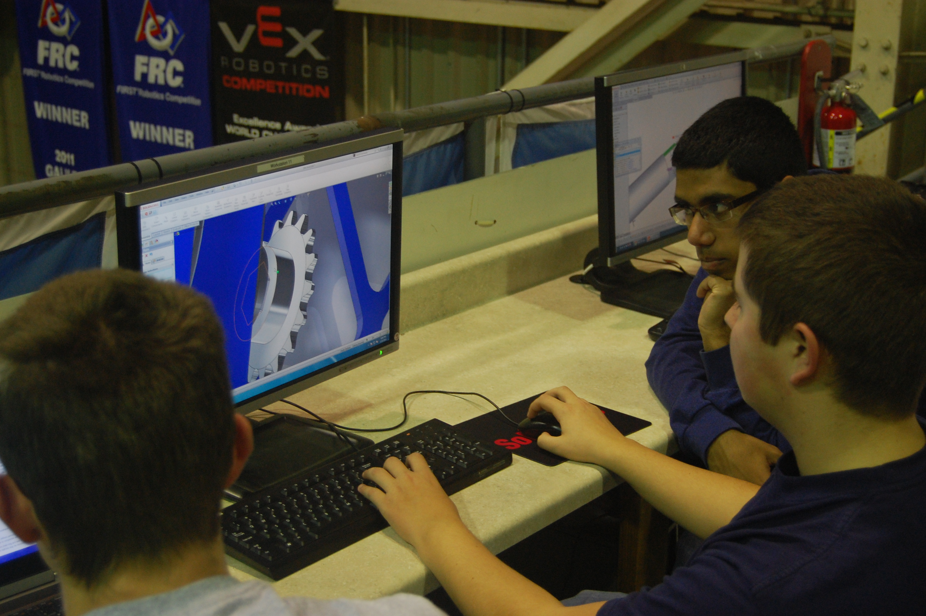
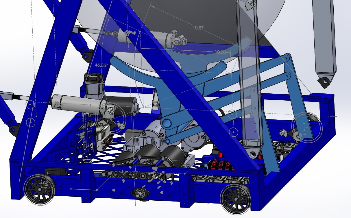
Drive Base Design
Today, the team began modeling parts for the gearboxes and chassis. We plan to design a drive base similar to last year but without a PTO on the gearbox. Tonight, we designed the gearbox output shafts, intermediate shafts and wheel shafts which will be sent out to sponsor Modern Machine Company tomorrow.
Action Items
- Continue gearbox design
- Continue testing and improving flywheel prototype.
- Continue testing puncher prototype, try to increase power.
- Rebuild catapult prototype, must be stronger and more stable.
- Programmers continue improving drive code and autonomous tuning with Tom.
- Improve catcher prototype with Dan.
- Possibly begin machining parts for the drive base.
Day 3: Prototyping continued, Autonomous strategies, and more
Autonomous Strategy
Today, we discussed scoring all three balls in autonomous. In autonomous, only the area directly in front of the low goal is guaranteed to be undefended. The strategy would involve starting with one ball in the robot, one in front and one behind. The robot would immediately drop an intake on each side of the robot and drive to the hot goal to score, dragging the balls with it. We also discovered that a banner sensor was able to pick up the reflective tape, meaning that the robot wouldn’t need to a camera to detect the hot zones.
We discussed whether it was more beneficial to shoot from afar or really close to the goal. Several team members proposed that shooting 2-4 feet away would be best since it would more than likely increase the robot’s accuracy. The fly wheel shooter was set up about 3-4 feet away from the goal and was able to successfully score
Catapult Prototype

A group today worked on a catapult prototype. A good amount of progress was made and it seems to be coming along well. The only things left to add are the rope, springs and hard stops.
Ball Catcher
Some of the students worked on a basic catcher prototype, making it from PVC pipe. They added a funnel to the top to increase the likelihood of the ball going in. It worked out well with some minor strengthening.
Programming
The programming team worked on a basic autonomous runner that uses threading. In essence, it allows for commands to be run while still allowing evaluation to occur. Also, in the event that a command should fail or timeout, the robot will skip the rest of the commands. One of the ideas that was brought up was separate compilation for the main code and autonomous routine to allow for quick changes to the autonomous without having to recompile the whole codebase.
Day 4: Prototypes, Coding, Drive base design
Catcher Prototype
Today, we continued work on the catcher prototype, making it higher and wider so that it can better catch balls from all angles. Although the catcher is promising, its large size may be a problem when packaging mechanisms for the robot.
Catapult Prototype
The catapult prototype was finished today. The shooter is very smooth and can be easily reloaded in less than 5 seconds. It is consistent and accurate from up close (~2 ft from high goal) but mediocre from midway to the white zone. This shooter suffers from inconsistency in ball positioning within the catapult which could be improved with a better ball cradle.
Flywheel Shooter Prototype
The flywheel shooter has been the most successful thus far with accuracy, precision, range, and simplicity. Because of its success (especially in scoring all 3 balls in under 5 seconds), we took it apart to replace the large wheels with smaller wheels while narrowing it to maintain ball compression with the smaller wheels. We hope to test this tomorrow.
Programming
Today, the programming team worked to get the 2013 practice robot up and running to test the drivebase. Several problems were encountered along the way. First, they had an SDK error on the robot which took them a long time to fix – eventually a cRio reflash solved the problem. Second, there was a problem with the wiring on the robot so they weren’t receiving any data from the TCP server. They eventually fixed the problem and now they are working on a way to graph the data from the robot in a quick and easily readable way.
Over the next few days they will also work on are prototyping some autonomous for the robot as we determined the autonomous is very important strategically.
Autonomous Strategy
We have determined that the autonomous period is critical to our success in Aerial Assist, allowing the robot to score up to 65 points. Because of this, we want our robot to be able to score 3 balls in under 5 seconds. The flywheel prototype is the most promising for meeting this objective.
Over the next few days, the programming team plans to start working on drivebase control loops for autonomous, using Overkill as a practice base.
Drivebase Design
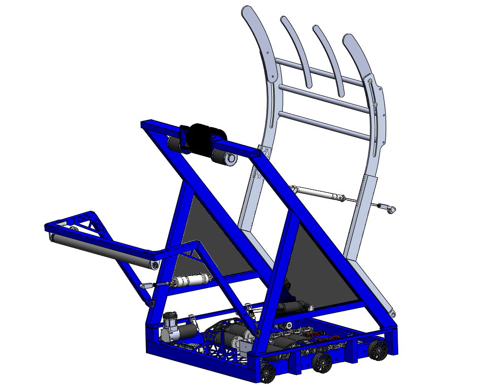
Today, work began on the robot drivebase, taking heavy inspiration from last year’s robot. The robot’s 6WD drivebase is the same overall size (28″ W x 27.75″ L) with wheel wells that can accommodate up to 1.5″ tread width. Today, we created a rough chassis in CAD and started work on the 2 speed drive gearbox.
The planned drive speeds are similar to last year (3 CIM motors per gearbox, 12:40 inital reduction, 15:48 low gear reduction, 28:38 high gear reduction, 3.5″ wheel diameter, 19.6 ft/s & 7.7 ft/s theoretical speeds). Due to the tight clearance between the 40T gear and the dog, the outer diameter of the dog will need to be reduced somewhat. Overall, this is a very similar gearbox to last year.
To determine the acceleration performance of our planned ratios, we performed a simulation of the drivebase accelerating. We decided to optimize the robot for 10-15 foot sprints and found that the ratios worked well with these goals. Furthermore, we found that while the 6 CIM drivetrain could reach 10 or 15 feet 10-20% faster than the 4 motor drivetrain, it drew much more power and could lead to premature battery drain.
Action Items
- Test flywheel shooter prototype.
- Test intake prototype with Mani.
- Continue working on drive base and gearbox design with Nagy.
- Compare all 3 shooter prototypes and decide on which we want to use.
- Continue work on drive code and autonomous planning with Stephen and Brandon.
Day 5: More Prototyping and Gearbox CAD
Flywheel Shooter Prototype
Today, we continued work on a new flywheel shooter prototype. The team determined that smaller shooter wheels would make the shooter more packagable in the robot. We made some great progress and we should be able to complete it tomorrow.
Design
Work continued on the drive gearboxes today. Based on the results of the simulation discussed yesterday, we decided that we would move forward with 2 3 CIM motor gearboxes but would also design 2 CIM motor gearboxes that could be swapped in if necessary. Although this would reduce acceleration, it could lighten the robot by up to 8 lbs.Today, we added the Bimba pancake pistons to the two speed gearbox assembly. We are moving forward with the previously discussed ratios of 4.2:1, 19.6ft/s in high gear and 10.6:1, 7.6ft/s in low gear. The CAD is almost done and is only missing a few components.
Programming
Today the programmers continued work on the graphing system for the robot. They worked on getting a TCP/IP server running on the robot and working out the technicalities of using a browser to monitor the stream of data from the robot.
Action Items
Finish Gearbox CAD, begin finalizing Drive base CAD
Day 6: Prototyping the Catcher, Building a New and Improved Flywheel, and Organizing Parts
by Jeffrey Kaufmann
New Flywheel Prototype
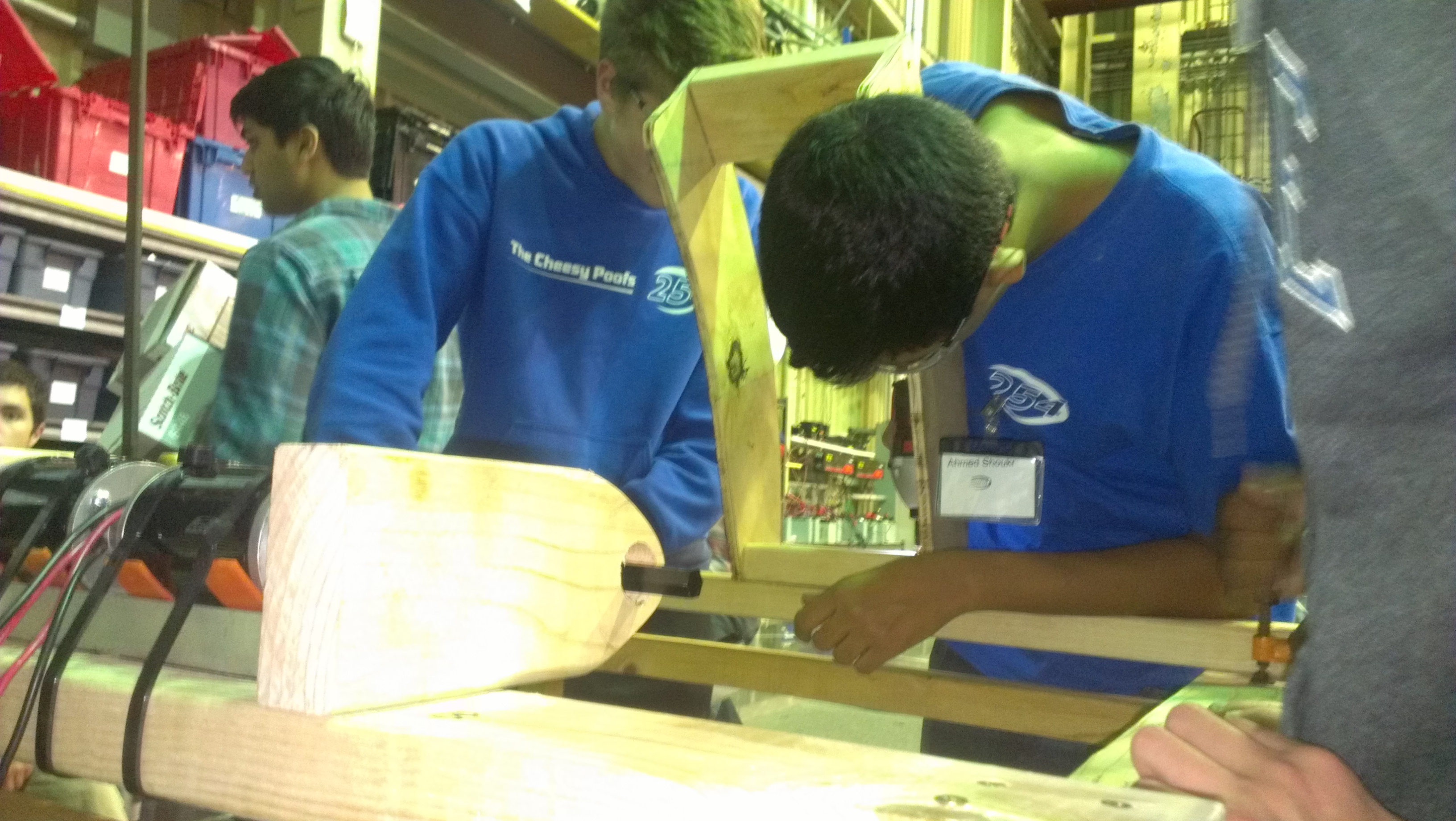
A team of students worked on the updated prototype of the flywheel shooter. The new prototype can shoot at an almost vertical angle, enabling the robot to toss the ball over the truss. It also allows for easier packing because its flywheel is smaller than that of the first prototype yet still retains the positives aspects of the original. Some problems occurred during the construction of the new wheel such as broken or splitting wood pieces delaying completion.
This piece had to be replaced. The team attached the curved piece of the flywheel that allows for an approximately 45 degree trajectory.
New Catcher Prototype
A group of students worked on fixing the second catcher prototype. This update will allow for a more mechanically robust device. The rope on the catcher and add a few metal pieces were overhauled today, resulting in a tighter, more stable and cleaner design.
After testing the new mechanism while driving the results were quite satisfactory. The great mobility of the drive granted the ability to quickly get underneath the ball and receive an almost perfect catch.
Programming
The programming team worked hard on the coding on day #6. Today they made it so that the robot can now serve HTML pages. Furthermore, they had to refactor some of the code. In conclusion, while they had to restructure the code, this change did not affect how the code behaved.
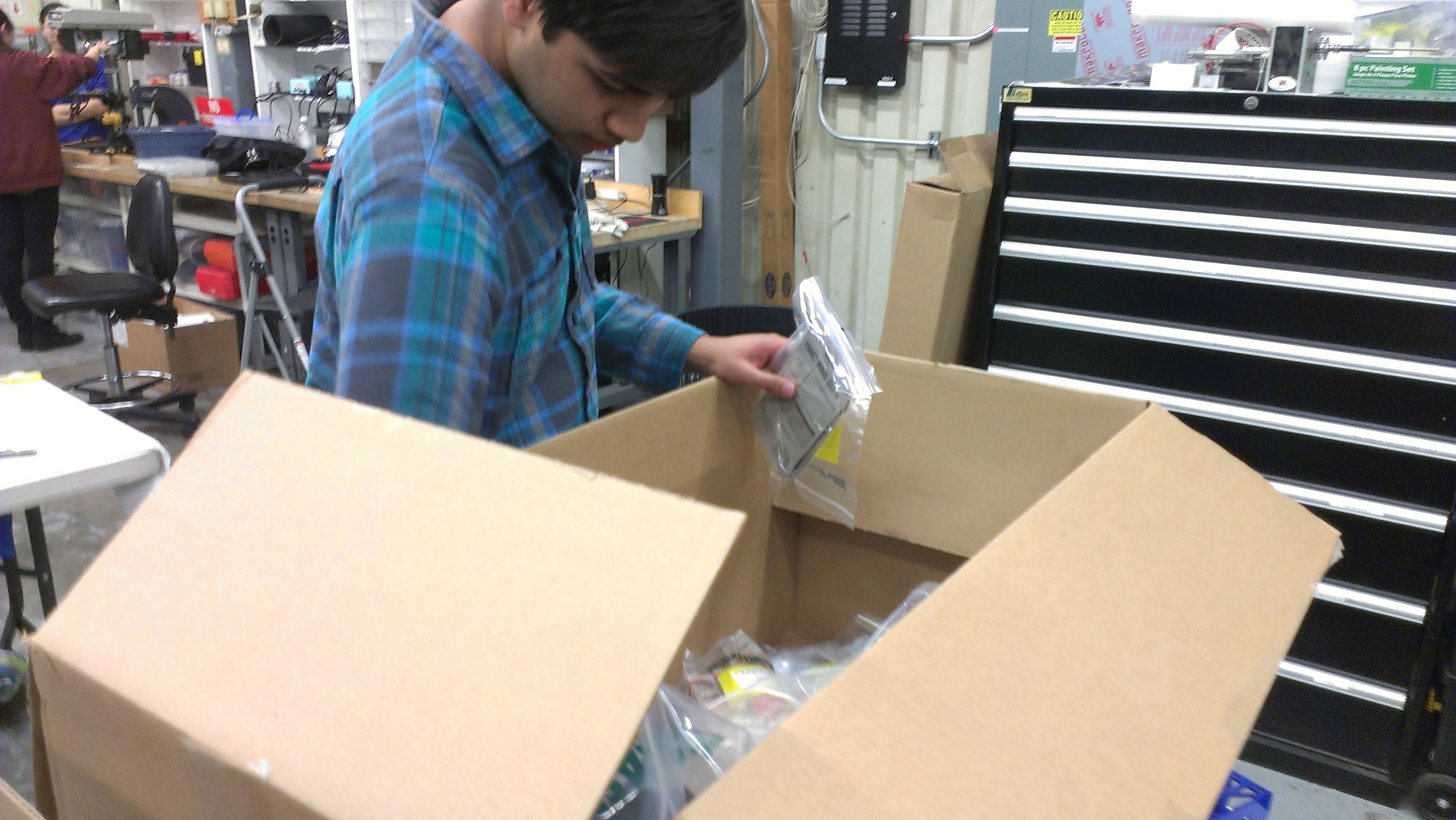
Organization of New Equipment
Recently, we received new equipment for the lab, such as soldering devices and other tools. Several students helped organize these new parts and categorized everything received into an Excel document, creating in effect an organized system of all the new equipment within a neat document.
Action Items
- Continue helping Abhi and Dan with catcher prototype and an add intake system.
- Continue helping Ahmed and Paul with shooter prototype improvements
- Continue testing
- Continue working on the drive base CAD with Andrew
Day 7: Prototyping, CAD, Testing, & Lab Improvements
Catcher & Intake Prototype
Today, several team members integrated the intake and catcher prototypes with the 2013 practice robot drive base to create a prototype robot that can catch and intake the balls. They removed the catcher arms from the back and front of the drive base and placed the intake in the back of the drive base. Additional planks of wood were attached to the walls of the intake to increase the compression on the ball while from the intake.
Several students began working on a new intake roller prototype. This new mechanism uses 1.5″ neoprene rubber rollers instead of the current 3.5″ blue bane’s bots wheels that are currently being used.
Shooter Prototype
A group of team members worked on further tuning the shooter prototype. They also performed several tests using different shooting angles and different distances from the goal in order to determine the optimum shooting distance.
Additionally, we began to improve the shooter prototype by adding reinforcements to the base and machining a new hood.

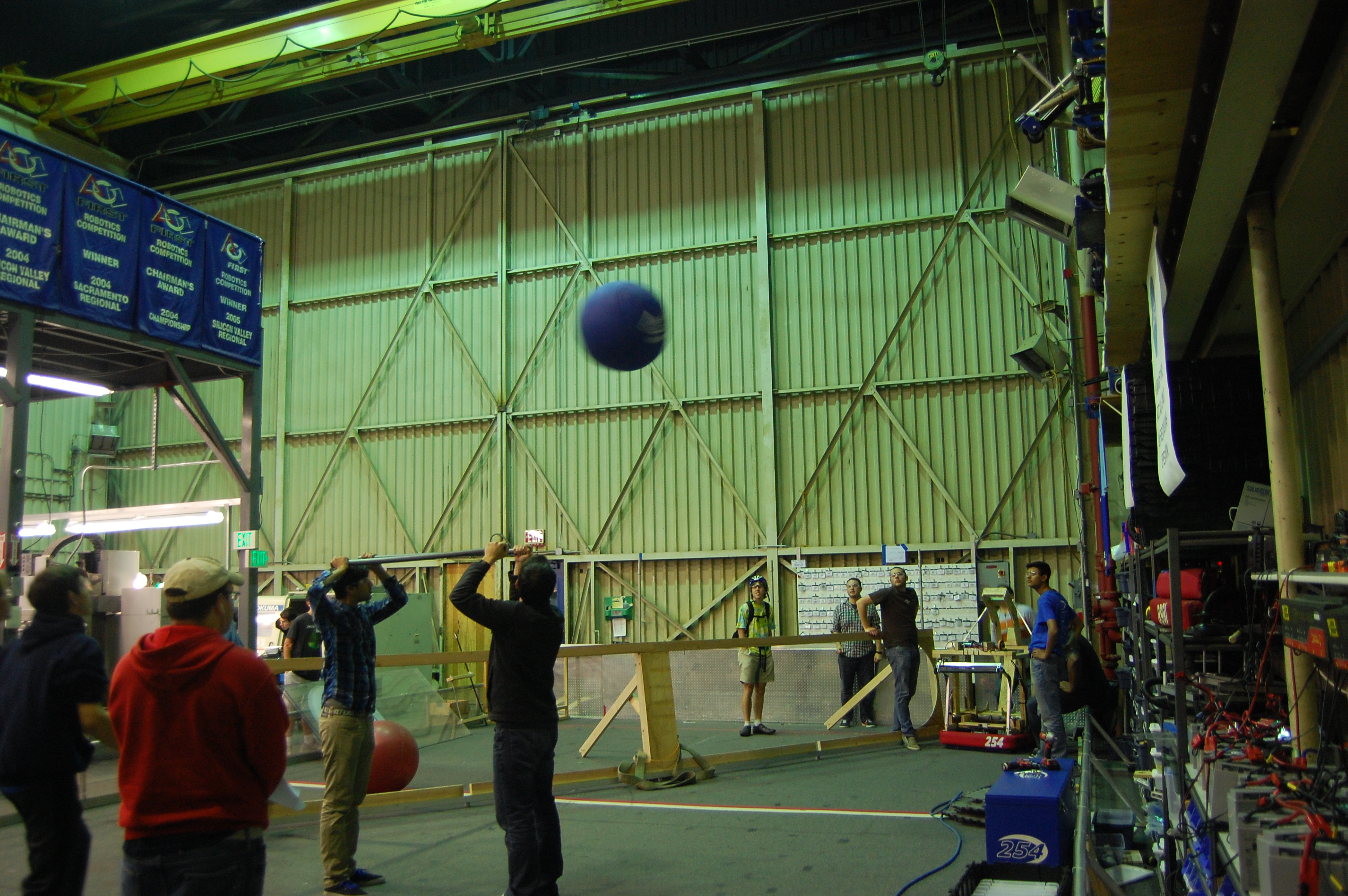
Prototype Testing
The groups working on the shooter and the integrated catcher and intake prototype came together to test whether or not it is possible for us to shoot over the truss using the current design. The conclusion is that the design will work, but it needs further tuning to be consistent. This test was done by using a “dummy truss,” also known as EJ.
The same group also tested whether or not it is possible for another robot to catch the ball as it is being thrown over the truss. The special constraint that we tested was whether or not the catching robot could start at the same position as the throwing robot and be able to drive fast enough to catch the ball. Although this robot has the same ratios as we are planning on using for the 2014 robot, it lacks a superstructure and is lighter, resulting in superior acceleration.
CAD
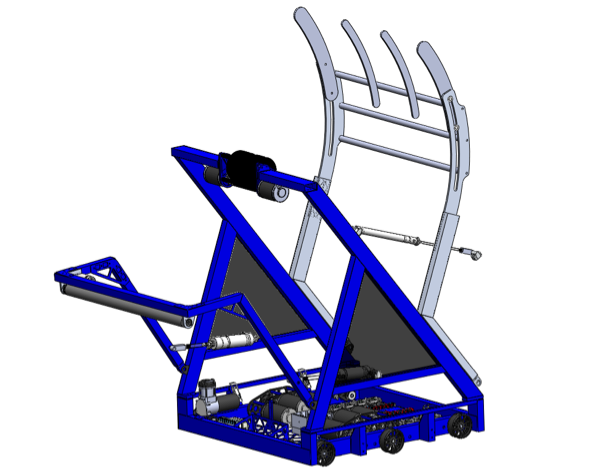
Work continued on the design of the drivebase for the robot. Right now the drive base is functionally identical to the previous year’s drive base. The only major changes have been the mounting points for the superstructure, which have been moved closer to the bumper mount to allow for a superstructure wide enough to hold the large balls in this game.
The team also got together to design the look of the rest of the robot. They discussed how to integrate the two intakes, the shooter, and the catcher into the robot and the overall design of superstructure. Right now there is a rough idea of how the robot should look. Further detailing will be based on the results of prototyping.
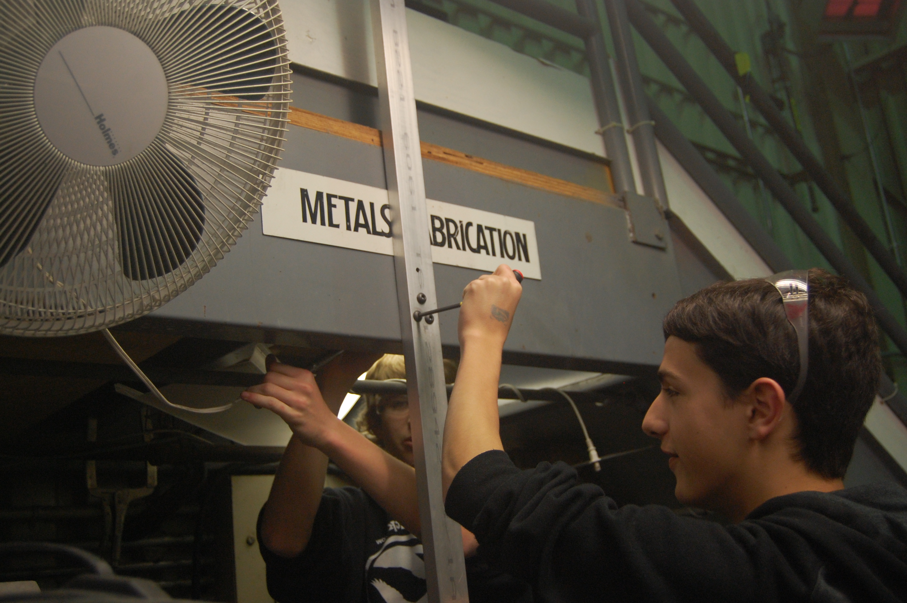
Lab Improvements
Today, we also worked on installing better light fixtures over the metals fabrication area in the lab. This will improve the lighting of the area, which will also improve machine quality and safety.
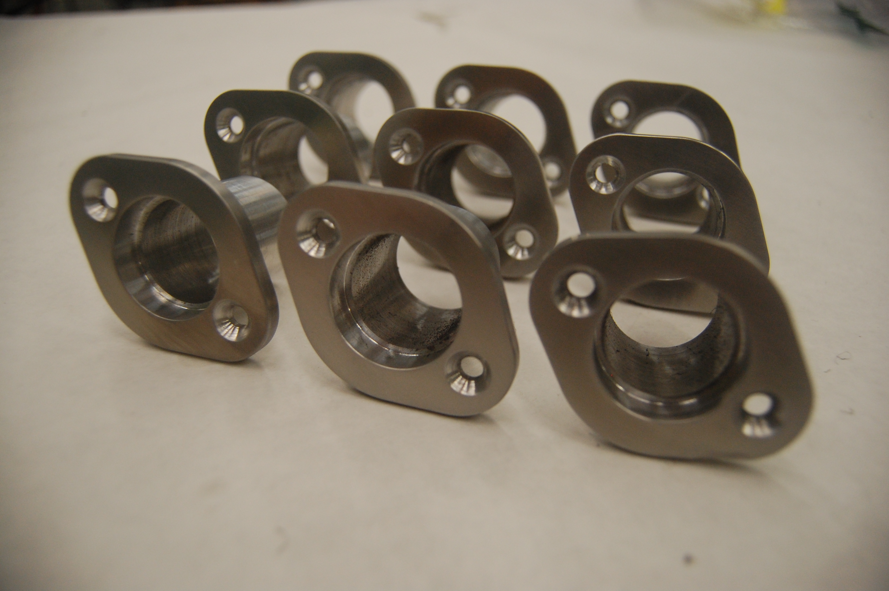
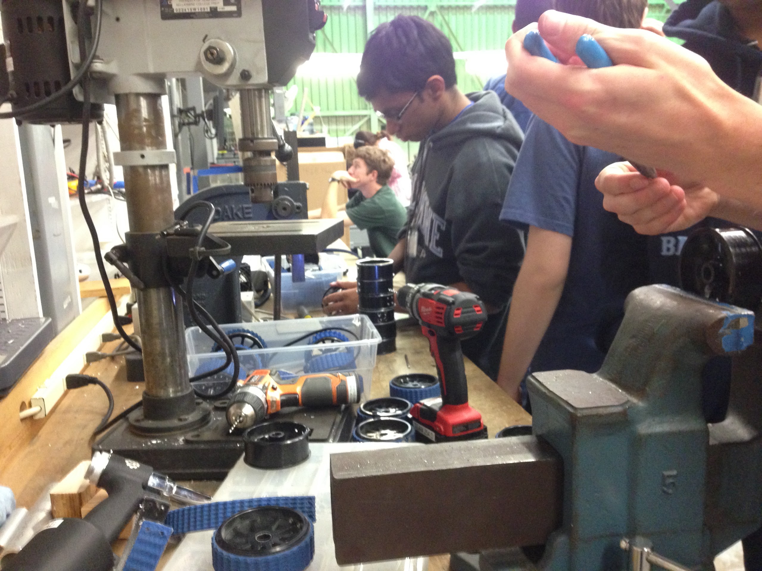
Manufacturing
The center bearing housings for the drive base were finished and polished today. As a result the manufacture of additional parts will begin.
Action Items
- Continue testing shooter prototype
- Finish manufacturing new intake prototype
- Finish drive base CAD
- Send baseplate for manufacturing
- Continue designing rest of the robot
- Begin manufacturing parts for the drive base
Day 8: Prototyping and Miscellaneous
by Christian and Michael Simeon
Catcher Prototype
Today, students lined the catching prototype with VEX field flooring tiles to help keep balls in the catcher by preventing them from bouncing off the PVC pipes and rope. Students also improved on the attached intake prototype. Additionally, they attached gyroscopes and encoders to allow the prototype to better recognize angles and ultimately better function. Students have begun testing for those encoders and gyroscopes added to the drive base. Sending data from the encoders and gyroscopes to a web browser with graphs and statistics on the robot will help with fine tuning the prototype.
The Shooter Prototype
An elevator system with metal bars and PVC has been added so that balls can be more consistently fed into the shooter. Additionally, the arch on the top of the shooter prototype has been modified. Later, metal and PVC were removed and replaced with a frisbee and cables.
CAD
Today the people working on CAD continued working on drive base. They mirrored the gear box for the other side of the robot and added it to the drive base CAD. They also added the electronics and other necessary components. Finally, they also made part drawings for spacers in the gear box.
Team members also continued thinking about packaging options for the superstructure. We have decided on having three pivoting arms for the robot’s two intakes and catching hood. All arms will be piston-actuated and are designed to fit within the 20″ extension rule. The intakes are bent to allow for rollers to contact balls as the robot spins to grab a ball. With straight bar intakes, the bars could push balls out of the way of the intakes.
We also discussed mechanisms for locking the hood in place during shots to prevent the balls from pushing against air pressure to reduce hood compression. Discussed mechanisms included an over-center piston linkage and a locking piston mechanism. We will likely move forward with the locking piston mechanism.
Miscellaneous
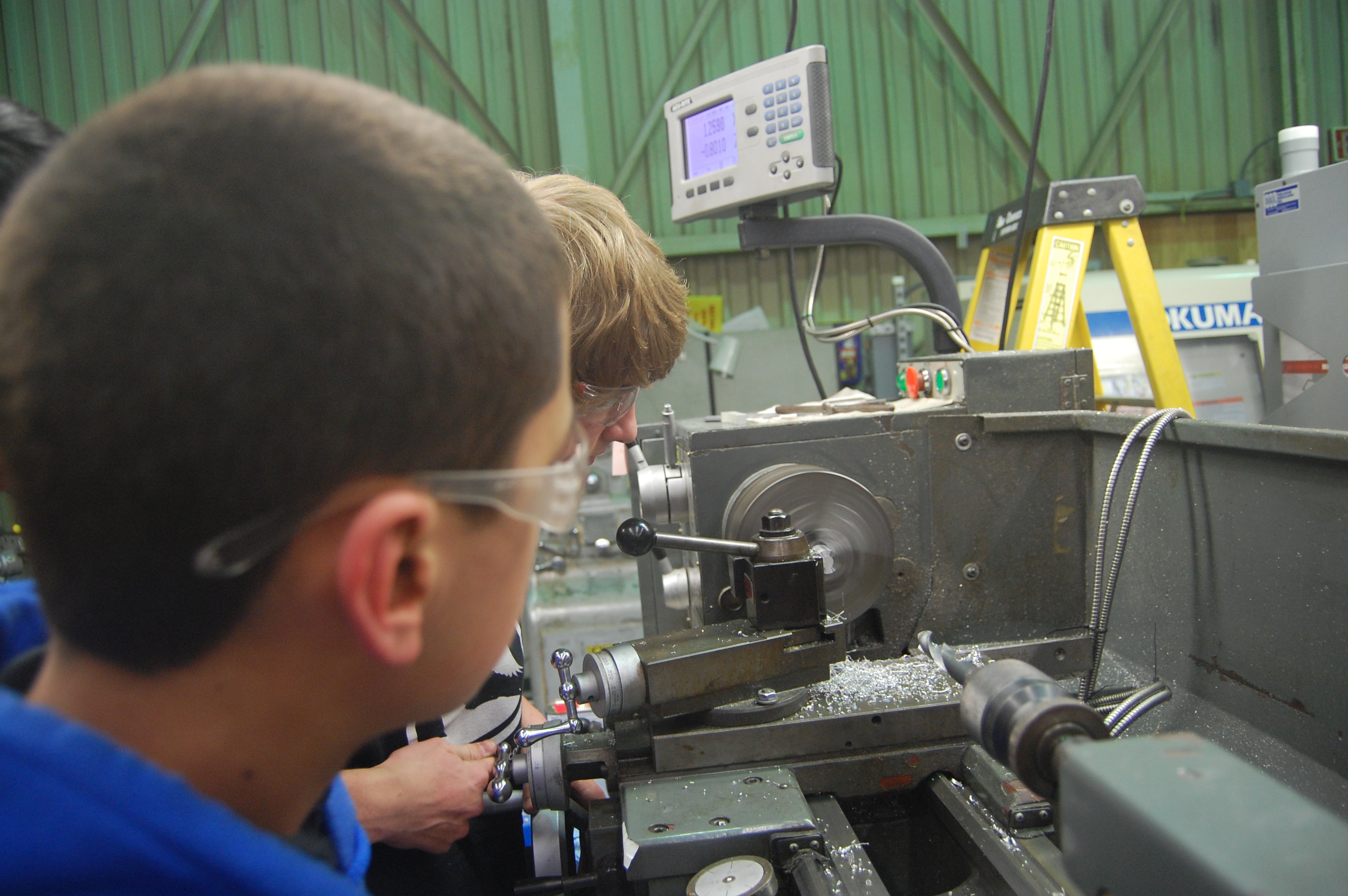
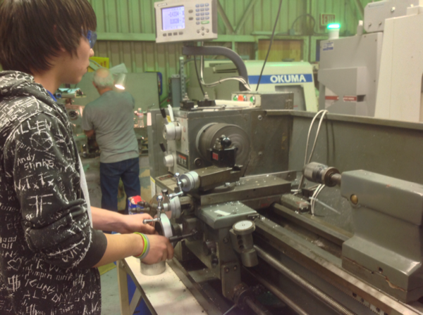
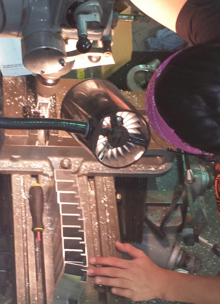
Students and mentors worked on the lathe to create standoffs for the gear box. Additionally, work continued on submissions for the Entrepreneurship, Chairman’s, and Media and Technology Innovation Awards.
Action Items
- Finalize entire drive train design and CAD with mentors to prepare for ordering the baseplate
- Finalize catcher prototype with Abhi
- Finalize control board design with Brandon Gonzalez, Chris Sides, and Abhi Kumar
- Work on pit display with Travis
- Brainstorm ideas for publicity releases for team social media sites for releases throughout the build season: for Jeremy, but he will not be there
- Create and maintain a Gantt chart for Mani
- Help Mani clean up
- Ask a leader for other tasks on the Trello
Day 10: Rest Day
In honor of our first day of rest of the season, here’s a GIF of the season’s latest dance craze.
Today, we didn’t meet at the lab. Some team members worked on CAD on their own.
Day 11: Prototyping, Design, CAD, and Testing
by Trevor Salom ’17
Programming
Today, the programmers worked on testing a VEX ultrasonic sensor to see whether the robot could use it to gauge its distance from the wall of the field. The VEX sensor was used as a temporary stand-in while the programming team awaits the arrival of the competition sensors.
In addition, they continued working on applications to graph the feedback sent by the robot.
Design
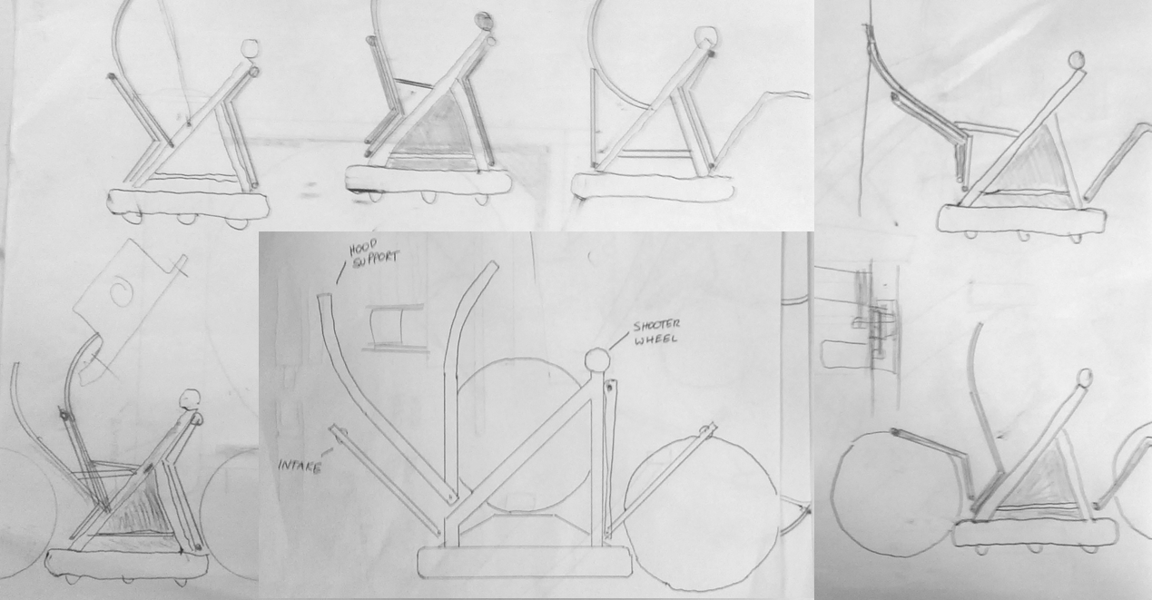
Today, we continued the design of the robot and continued detailing the main intake, the shooter wheel and the actuating hood. The shooter is powered by two mini CIM motors with power transmission through small GT2 timing belts. The front intake has a 550 motor mounted on the end of the arm with a two-stage belt reduction aimed to give a roller surface speed around 15 ft/sec. This speed was determined by estimating the average robot speed while intaking (10 ft/s) and determining the amount of time we hope for an intake to take.
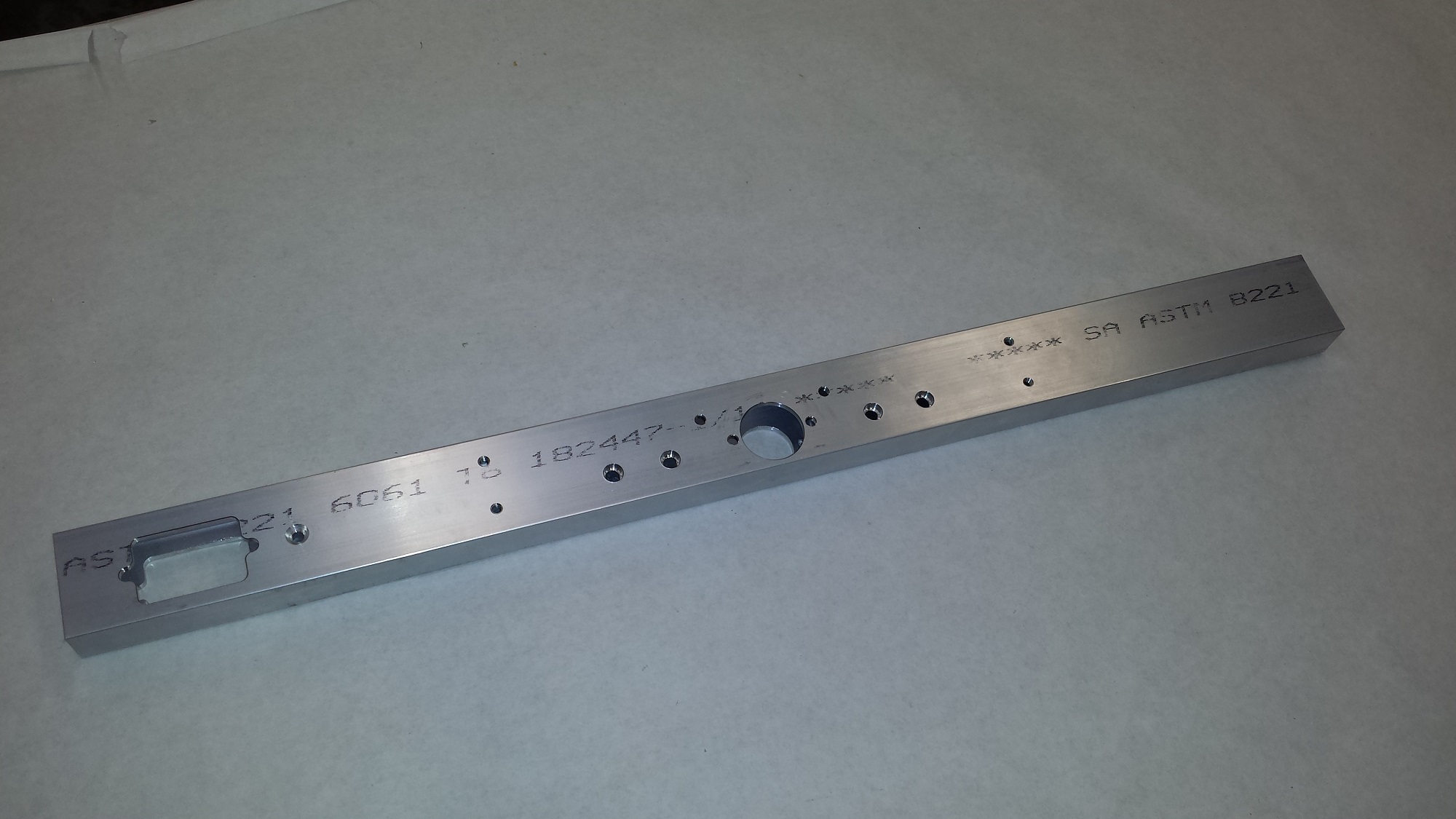
Furthermore, we finalized the design of the baseplate and continued work on the design of a drill holder.
Manufacturing
Today, we began making the outer bearing housings. A large order of material arrived today from our aluminum supplier. The aluminum plate for the robot bellypan was dropped off at sponsor BAE systems for waterjet cutting. We expect the baseplate to be cut on Monday.
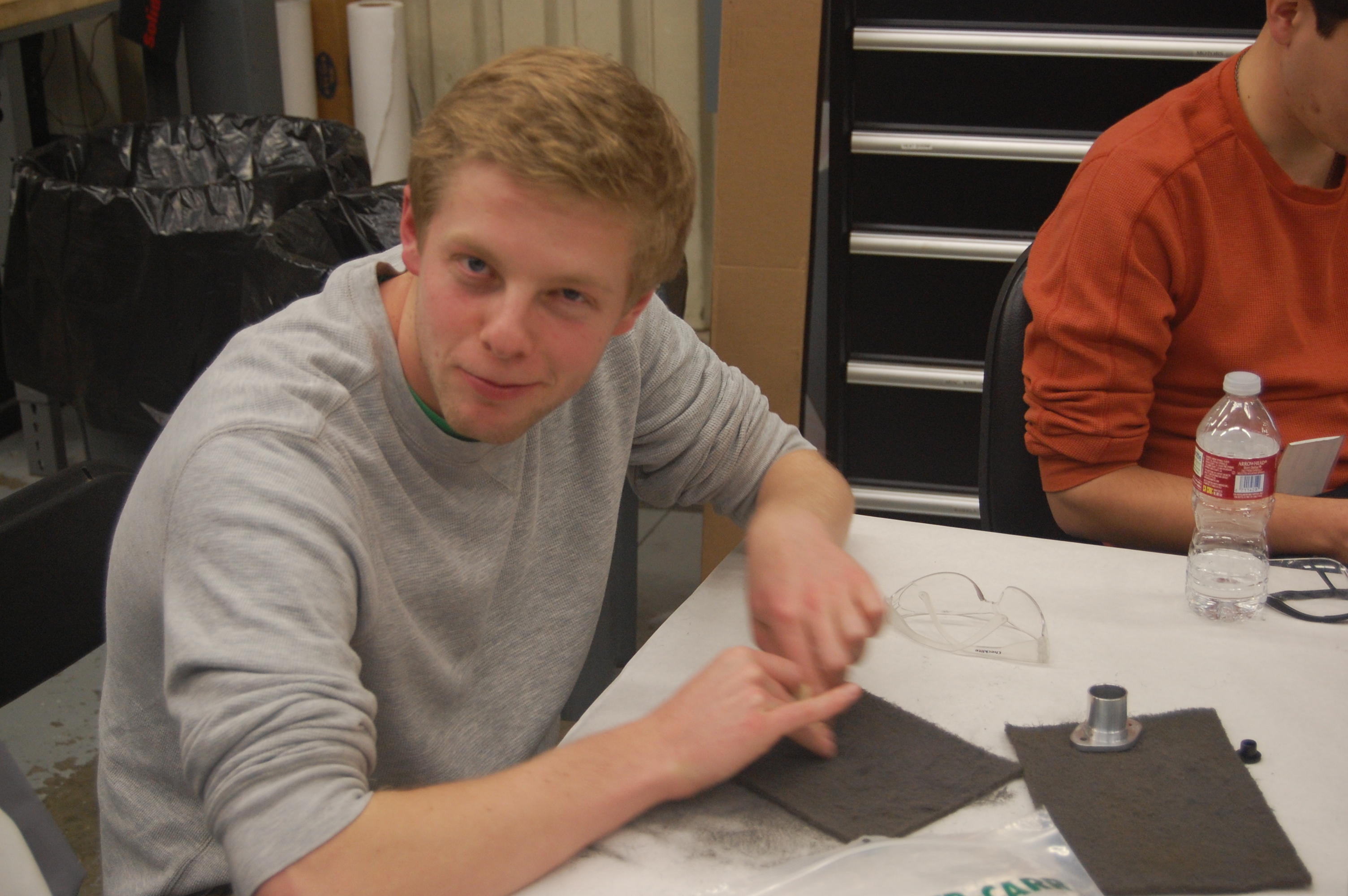
Furthermore, a number of team members cut tread today. This tread will be used on practice wheels for existing robots and may eventually be placed on the competition robot (once its wheels are made).
Roller Intake Prototype
Work was also started on building a more refined version of the roller intake prototype. The intake will be raised and lowered by pistons, and will be based on a CAD drawing of the final design.
Action Items
- Finalize Robot Design and CAD under Andrew Torrance and Mani Gnanasivam
- Refine Intake Prototype under Dan Judnick
- Programming and related testing with Brandon or Stephen
- Help out the Media Team under Kevin or Maxwell
- Ask a leader or mentor or request access following the instructions on the whiteboard to see what other tasks are listed on the Trello.
Day 12: Design Review and Further Prototyping
by Dan Ngo ’17
Design Review
The highlight of the day was the design review, during which the team congregated to discuss and possibly finalize the strategy and conceptual robot design thus far. The team decided that its overall strategy would be aimed at being able to first self score all three balls in autonomous. This removes any risk of relying on teammates during this valuable portion of the match. Subsequently, in teleoperated mode, general scoring would be prioritized. Assisting, while useful for qualification points, will likely only become significant in elimination matches.
Regardless of strategy, we agreed that the robot should be able to perform all the tasks in the game (shooting, passing, catching, etc.). We determined that a flywheel shooter aligns with these goals and packages nicely in the robot’s envelope. Additionally, to be able to score all three balls in autonomous, the team would first need a mechanism to hold and feed them into the shooter. This is currently being prototyped.
Programming
Team members continued work on integration of the ultrasonic sensor. We also worked on making programs to remotely access feedback from the robot, to ease autonomous testing. We also installed new, smaller, joysticks on the control board. These joysticks use hall effect sensors instead of potentiometers for more reliable and precise control.
Manufacturing
Today, groups worked on machining parts for the gearbox, the ongoing arm prototype, and started the feeding mechanism prototype.
Action Items
- Continue intake prototype
- More testing and coding
- Work on the feeding mechanism prototype
Day 12.5 – Testing the Lidar
Today, the team tested an advanced Lidar Sensor solution. Extensive testing was performed (approx 30 min).
Day 13: Intake Construction, Flywheel Prototype, CAD
by Jeffrey Kaufmann
Flywheel Prototype
Today, work continued on the automated ball loading mechanism for the flywheel prototype. This “popper” will use two pneumatic pistons to quickly and precisely load balls into the shooter for more consistent and realistic testing. Tomorrow, the entire shooter will be mounted on top of the robot drive base along with the intake and to test the integration of the three systems.
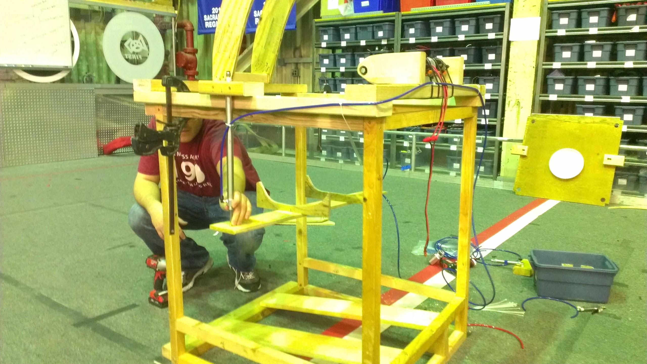
Intake Construction
Other team members worked on creating a new prototype intake. This intake was created to the dimensions currently in place in the robot CAD model. It will be able to flip down with two pistons. The intake will utilize one mini CIM motor to drive the roller. When the intake is down, it can suck a ball and pull it up against the bumper. When the intake comes up while holding a ball, it pulls the ball into the robot. This will later be integrated with the shooter and “popper.”
Later in the night, the intake was finished and tested with the robot driving around. While this test did not utilize pneumatics, it did show that the intake successfully could pick up balls both while stationary and moving.
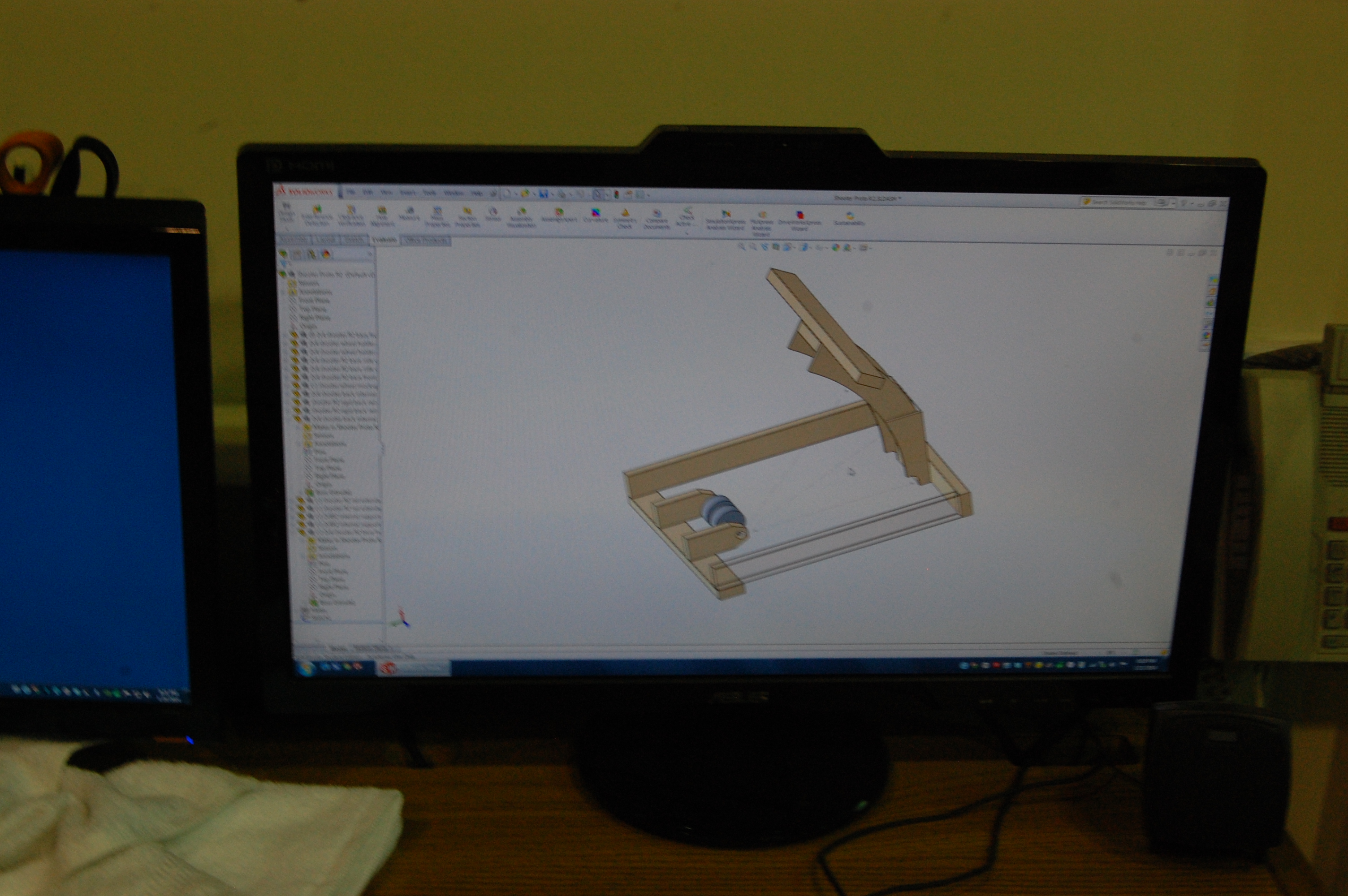
CAD
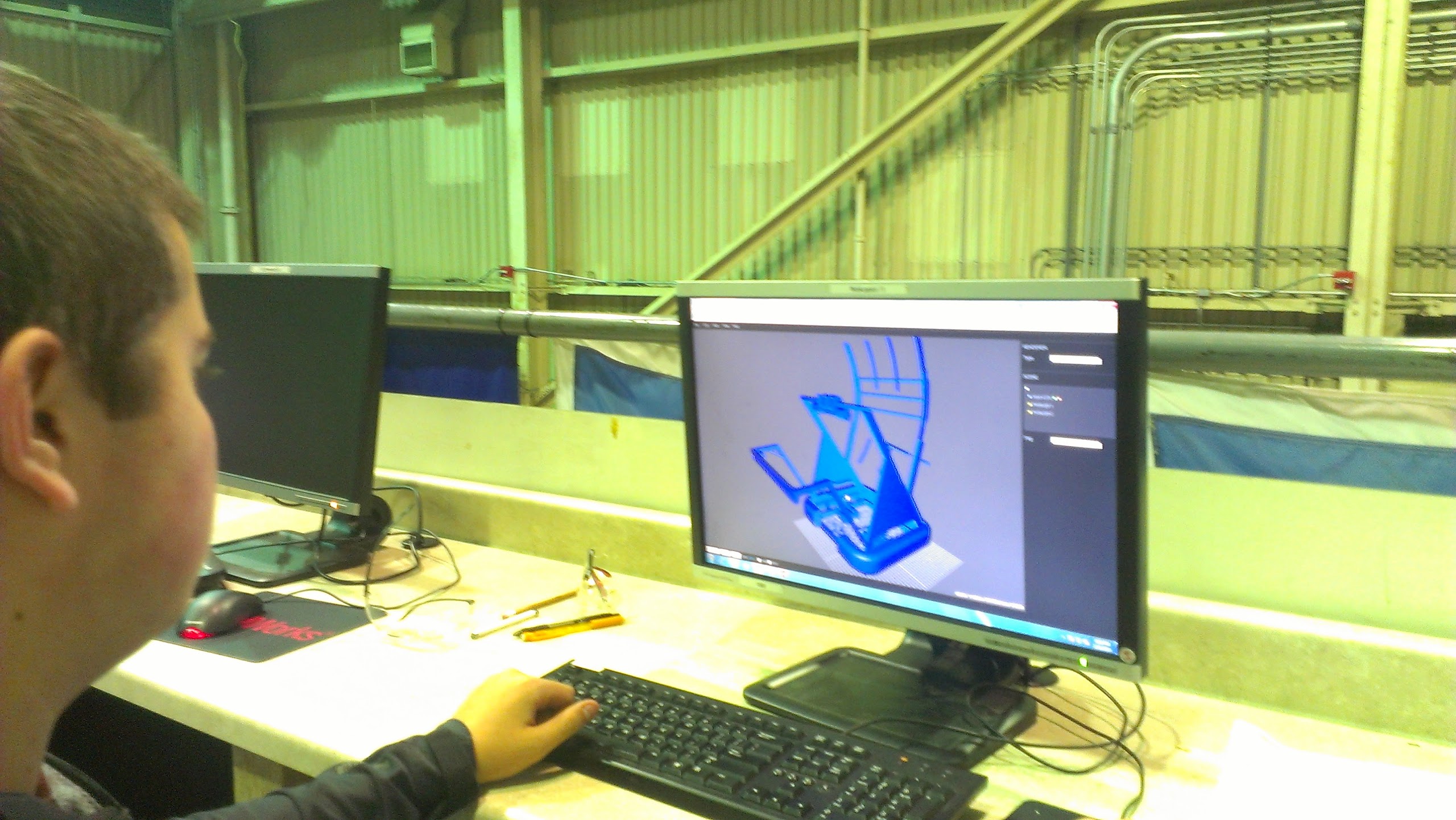
We also worked to create 3D render of the robot that can be used for the touch screens in the pit. Specifically, we worked to convert the current CAD model of the robot into a website that can be manipulated on a touch screen. This will be a fun, interactive way for visitors and judges to explore the CAD model of our robot.
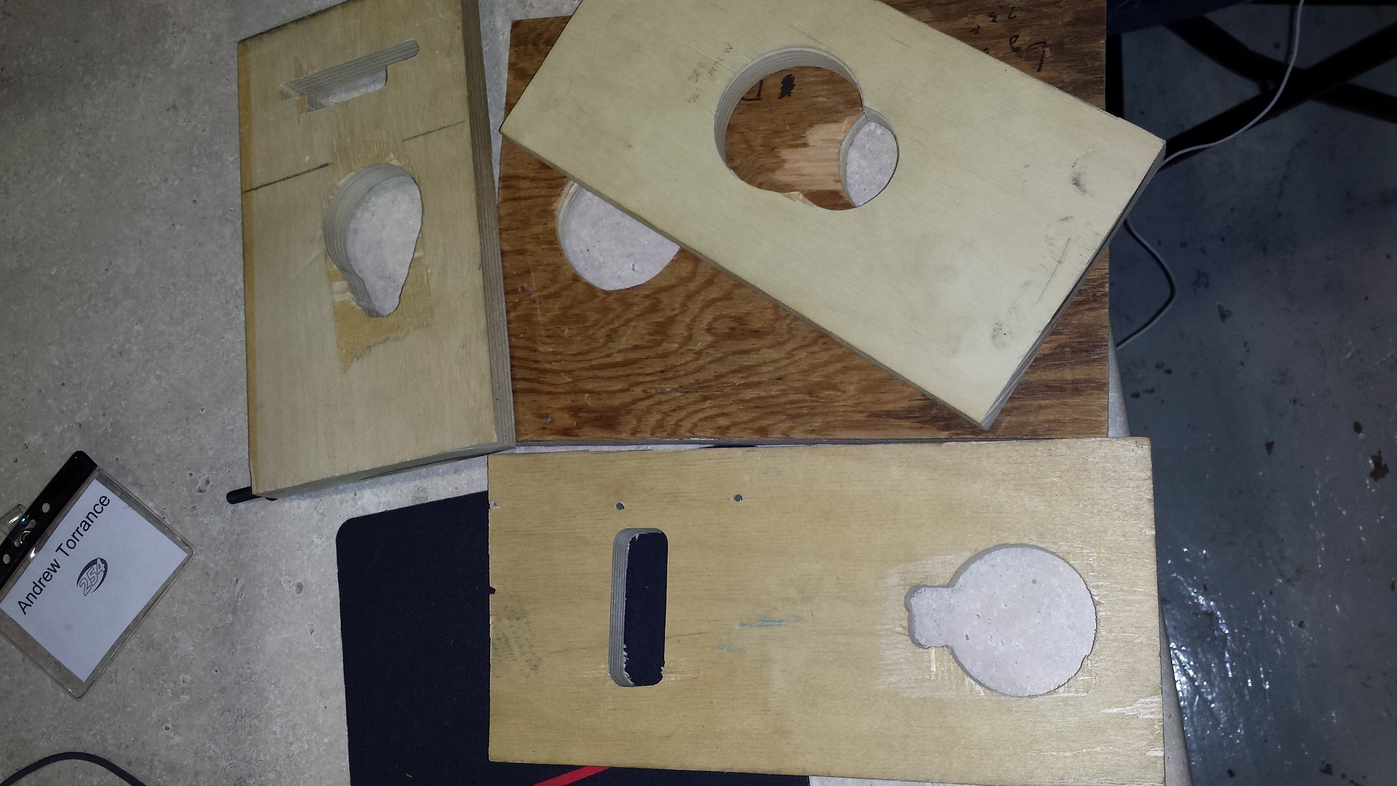
In addition, we continued work on the Cordless Drill Holder. Some students were finishing up the CAD upstairs and figuring out the final dimensions so the organization unit can fit in one of our travel crates. Others were using the drill press and mill to make precise prototype holes in wood for the drill chucks to fit in. These test pieces were then used to get accurate dimensions in the CAD that will be later sent to Good Plastics to be professionally routed in blue HDPE plastic.
Action Items
- See the Trello boards!
- Continue work on Intake construction
- Keep testing 3-D render
- Finish Flywheel Shooter Prototype and integrate with Intake prototype and Overkill drive base
- Finish CAD of Cordless Drill holder
Day 14: Working Robot Prototype, CAD, Chairman’s Award Begun
by Christian Bagamaspad and Michael Simeon
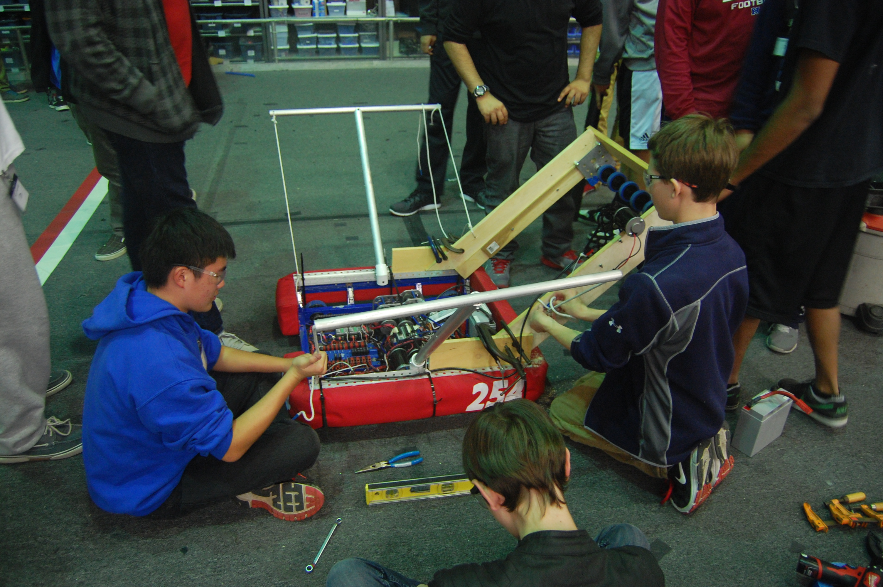
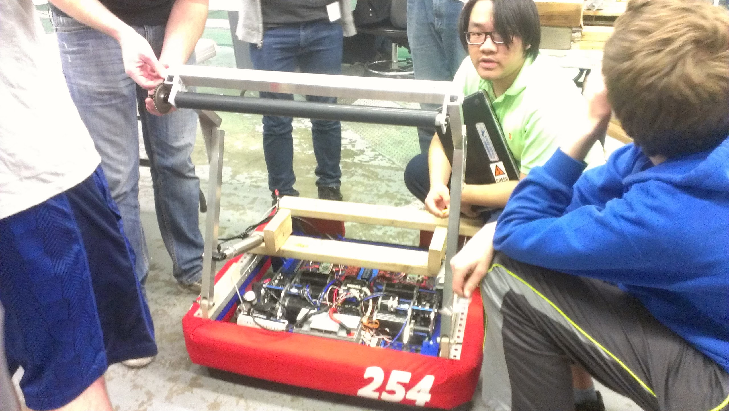
Robot Prototype
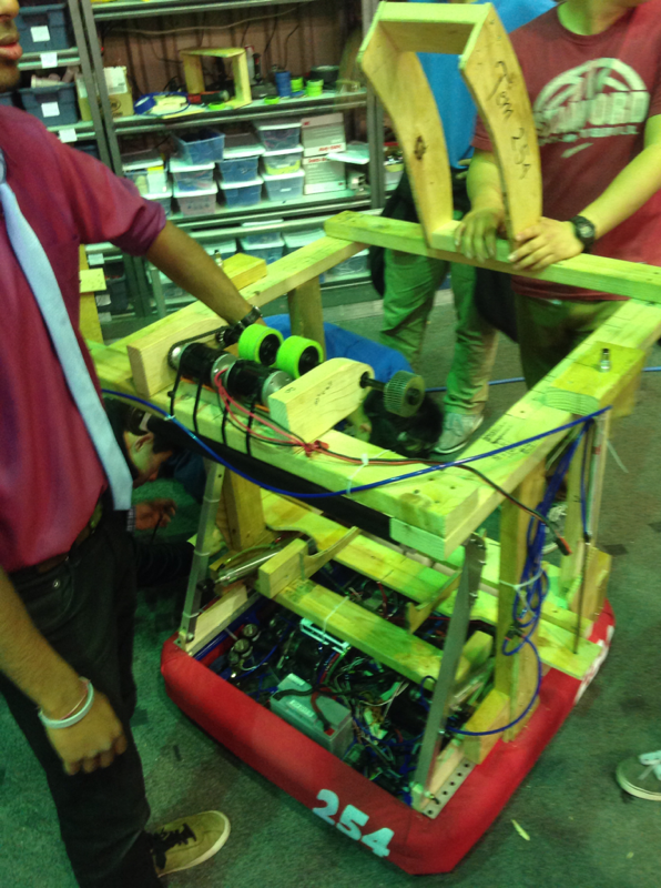
The robot prototype changed considerably today. First, the shooter prototype was mounted to the 2013 drive base. The robot can now drive, intake, load the ball, and shoot in one test. Results were very promising and tests showed the robot can pick up and hold two balls, sequentially index and shoot them into the goal. Later, shots will need to be fired more consistently, and the “popper” piston mechanism will need to be more robust to provide better shots and prevent the ball from getting jammed. This mock up prototype of the robot could possibly be used by programmers for early autonomous testing. This is one of the first times in recent years that team has built such a large compilation of other prototypes. Due to the simplicity of its design compared to previous years, this prototype will actually be somewhat similar in functionality to that of the final robot.
CAD
Today, the CAD team worked on the ball lifter assembly and piston positioning for the 2 position hood. We also went through the drive gearbox CAD to ensure everything is in ship shape before manufacturing begins.
The team also worked to finish up the 3D model of the cordless drill holder, finalizing the hole placement and overall ascetics. Once approved, the CAD model can be sent to Good Plastics to have it routed.
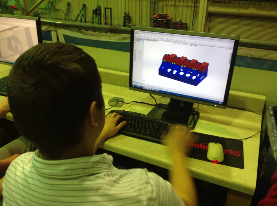
Additionally, others started work on the control board CAD, starting with the process of designing the control board plates itself. They also found and selected all the screws for the control board. Next, the control board’s button layouts will need to be designed and modeled.
Award Submissions
The drafting of the Chairman’s Award Essay thesis began today. Team members brainstormed and wrote tentative theses in preparation for outlining over the weekend. Additionally, they also reviewed previous submissions for the Chairman’s Award and discussed the implicit intent of the thesis. They decided that the underlying message of the essay should emphasize the development of the team since its 2004 Chairman’s Award victory and how the team has continued to set a new direction since then. The team also plans to portray how it has further emphasized outreach and how inspired others in our local community and abroad.
Manufacturing
Today was a slow day on the manufacturing front. The primary task of the day was shortening the drive gearbox piston spider standoffs.
Pit shelving
Today, students worked on organizing the pit storage shelves. Prior to today’s work, the shelf storage had been bound by tape, but now, the tape has been replaced with Velcro straps and certain beams were marked to point to the holes used in assembly. This will help save time during pit set up and tear down and prevent us from having to keep reusing expensive tape to simply bundle the segments together.
Action Items
- Check the Trello!
- Test and improve intake and shooting mechanisms on the robot prototype
- Finalize and approve the model of the cordless drill holder to be sent to Good Plastics
- Look through the website and all its pages and condense into a Google Doc a list of everything outdated, inaccurate, or otherwise unfit for the website.
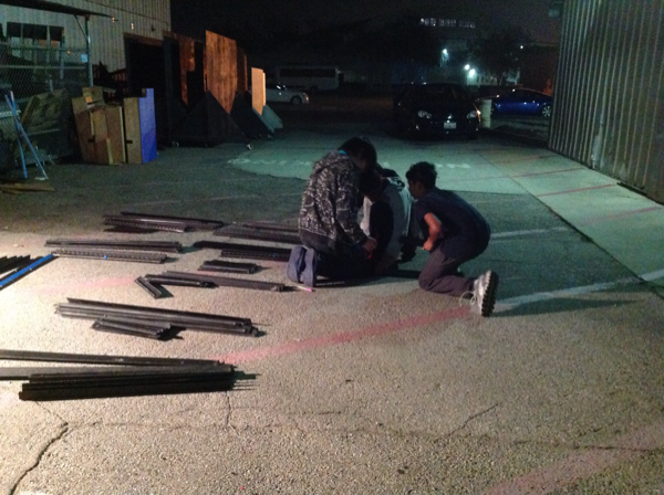
- Organize outside storage area to make obtaining materials faster, simpler, and safer.
Day 15: CAD, Machining, Prototype Robot, Programming, S’MORES!
by Clay Rosenthal
Important Reminder
Wear safety glasses on bottom floor of lab at all times! Even if you are not machining or there are few people in the lab this is a requirement.
CAD
Today, work continued on the design of the inner plates of the hood. We also investigated the use of a Watt’s linkage for lifting the ball into the shooter. The Watt’s linkage has a large (approximately) linear region in the center of its travel that we could use to lift the ball straight into the shooter. A separate lifter idea used a 4 bar linkage to lift the robot. Work on both of these projects will continue tomorrow.
On the drill holder, holes for the large Milwaukee and DeWalt drills were prototyped today and the CAD was approved. This will soon be sent to Good Plastics for routing.
Buttons were added to the CAD of the control board to our operator’s specifications.
Machining
More pieces for the drivebase chassis were cut today including 4 frame side rails. Also, middle bumper supports were machined with the mill. These will eventually be riveted together with the rest of the chassis and sent out to welded and powder-coated.
Robot Prototype
The prototype was tested today. The robot was able to intake, “pop” the ball, and shoot it with driver control in the afternoon. The robot has balance issues that can cause it to tip and fall on occasion, as shown in yesterday’s post. In the evening adjustments were made and there arose complications involving the pistons for the popper not rising at the same time. This was fixed but will need to be perfected. The hood was extended to change the firing angle and the fly wheel had an extra wheel added. A button was added to the intake to help with autonomous. Also a more solid back plate was added to help keep the ball in. All of these modifications are making the shots faster and improving consistency and accuracy.
Programming
Today, the programmers first worked on designing an auto-intaking control loop to hold a ball in the intake off the ground while another ball is in the robot. This will allow the robot to transport multiple balls in autonomous. The control loop started very rough, simply running the intake whenever the ball lost contact with a bumper switch. Later, we added an encoder to the roller and designed a control loop to smooth the intake.
The second thing that we focused on today was the data grapher webpage. We decided what the layout of the JSON file that we send would be. We eventually decided to go with one big file that would contain many separate JSON objects for each graph.
Finally, the programmers worked to implement a simple two-ball autonomous routine. While it takes far longer than ten seconds to run, it is a good proof of concept.
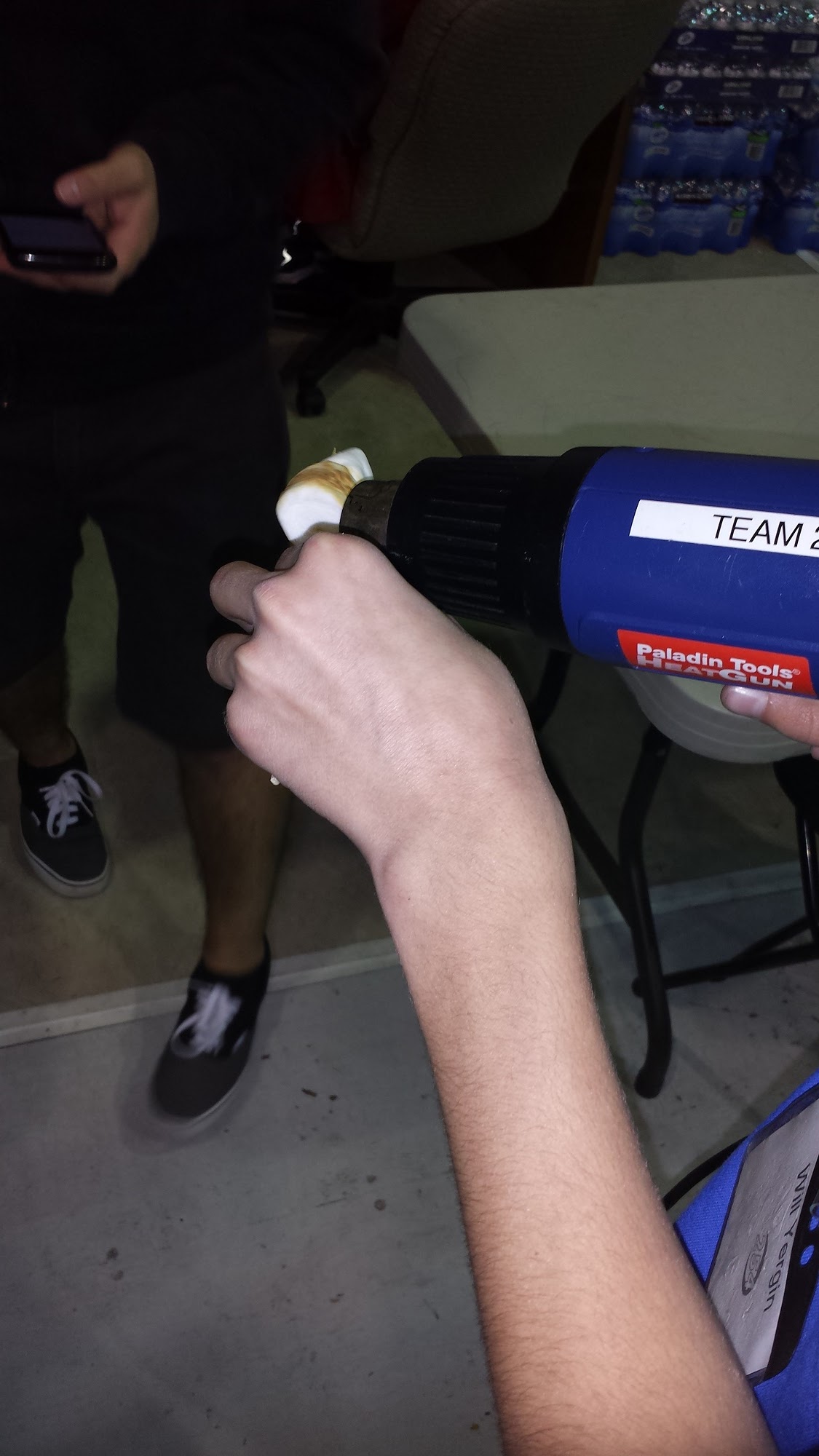
S’mores
Late at night, we made s’mores using a heat gun. It worked really well and the s’mores tasted great! We should do this more often.
Action Items
- Check the Trello!
- Finish refurbishing of the pit shelving crate (repaint, attach hinges/latches, add wheels)
- Programmers: test flywheel controller and intake state machine.
- Begin CAD of the Battery Cart.
- Continue improving robot prototype, make more consistent.
Day 16: Programming, and Prototypes
Programming
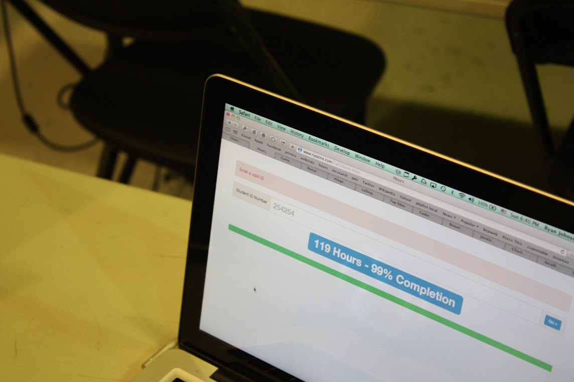
Today, the programmers worked on two major projects and a smaller one. The two larger projects were a data logger for the robot and an app for members to check their FRC Hours. The smaller project was to get Adobe products which had been generously donated to the team onto a few of the lab computers.
The Data Logger will return data from all the parts of the robot and plot them on a graph.This will help the programmers to detect what is going on in different parts of the robot and at what time it happened. They plan to fix the single plot graph and make the logger capable of tracking different sub-systems.
The FRC Hours mobile app makes viewing member hours more accessible. This should make it easier for members to track how many hours they have completed and how many more they need to do. The programmers plan on adding more functions onto it later, including even a signup system for the builds.
The final thing that the programmers worked on was putting Adobe InDesign, Photoshop, and Illustrator onto the lab computers. This took a lot of time as there was one CD of each to go around, and ultimately, they could not finish installing each by the end of build.
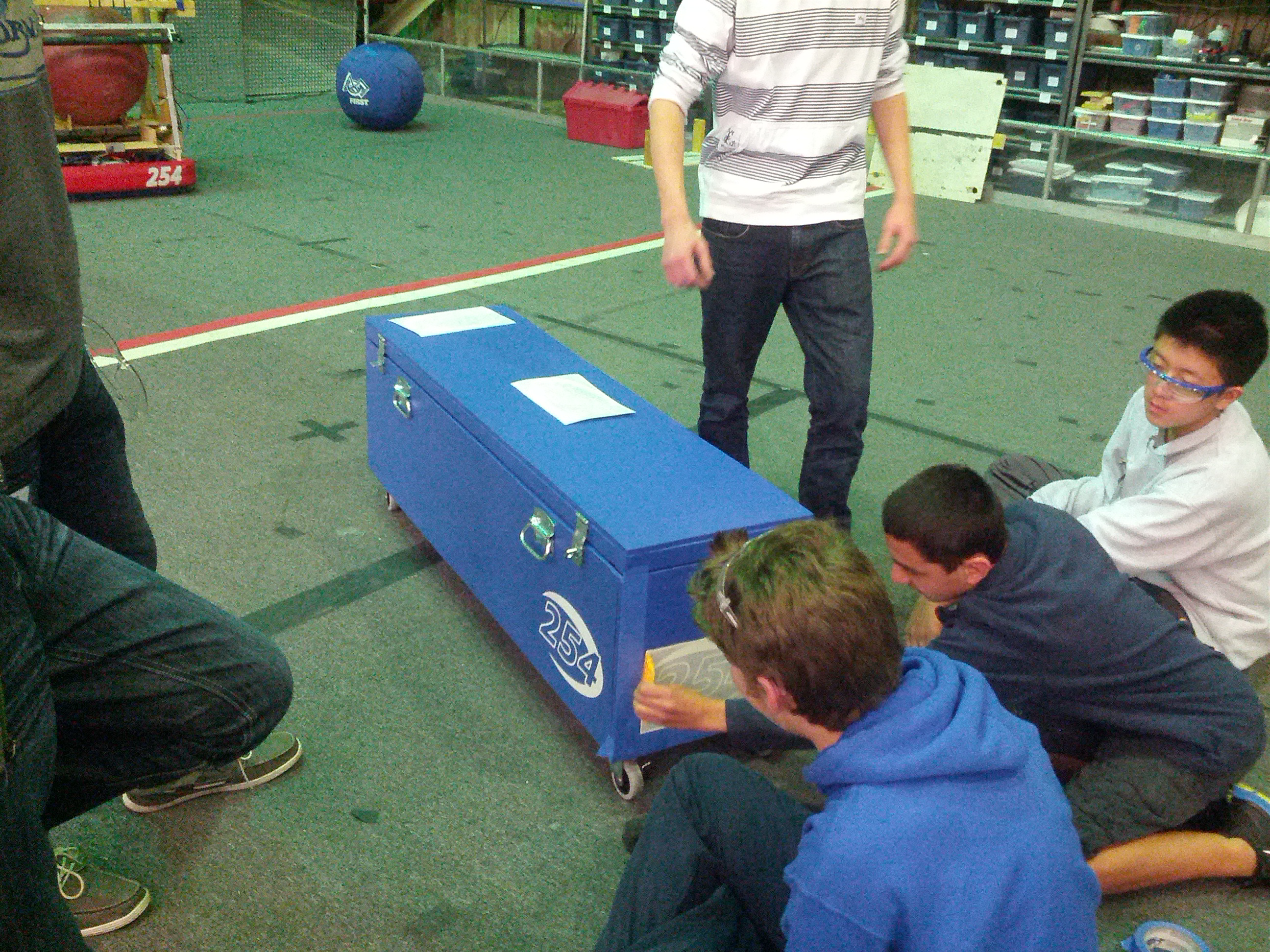
Pit Shelving Box and Robot Shipping Crate
Today, we also upgraded the pit shelving box. The base was re-painted in two coats, a flat coat and then a secondary semi-gloss coat, all in blue. The cover of the box was also redone, using less pieces so that it looked cleaner. Two handles and four wheels were added to enhance box mobility. The hinges were also supplemented with gas springs to hold the lid open during loading and unloading.
Members also touched up the paint on the shipping crate, last painted in 2011. The two new boxes look great and we’re excited to bring them to competition!
Prototype Catcher
Students built an improved catcher that more closely resembles the CAD (one that can actually fit on the robot). They attached pistons to the catcher so it could open and close. They also brainstormed the structure of the side of the catcher. They were unable to finish the rest of it due to a lack of material, which will all arrive by the next build. They will then attach the material to the side and the back of the catcher so that the ball will not fall out of the catcher upon being caught. Additionally, they added some blue paint to the structure of the robot prototype.
Manufacturing: Bumper Supports
Students also used the mill to make the metal bumper support brackets, which are needed to attach the bumper to the robot drive base. They were able to finish this and will soon be riveted together and sent out to be welded.
Action Items
- Sign up with Kevin Vincent, Greg Magarelli, and Peter Feghali if you are interested in helping or have the skills to contribute to the media team (in short, if you want to be a part of any or all of the following: photoshop, graphic design, photography, video design and editing, 3-D animation, website operation, social media updates, publicity releases, and CAD rendering)
- Help Stephen and Brandon install Adobe software on the lab computers
- Brainstorm additional functions for the 254 Hours Mobile App for Brandon and Stephen
- Brainstorm ideas with Ian Kirkland for media posts
- Machine the front brace, back brace, and top plate for the cordless drill holder.
Day 17: Rest Day 2
Today, there was no official meeting at the lab. However, several team members continued to work on robot design.
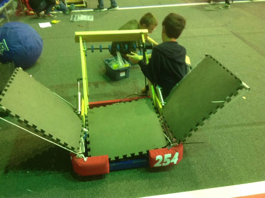
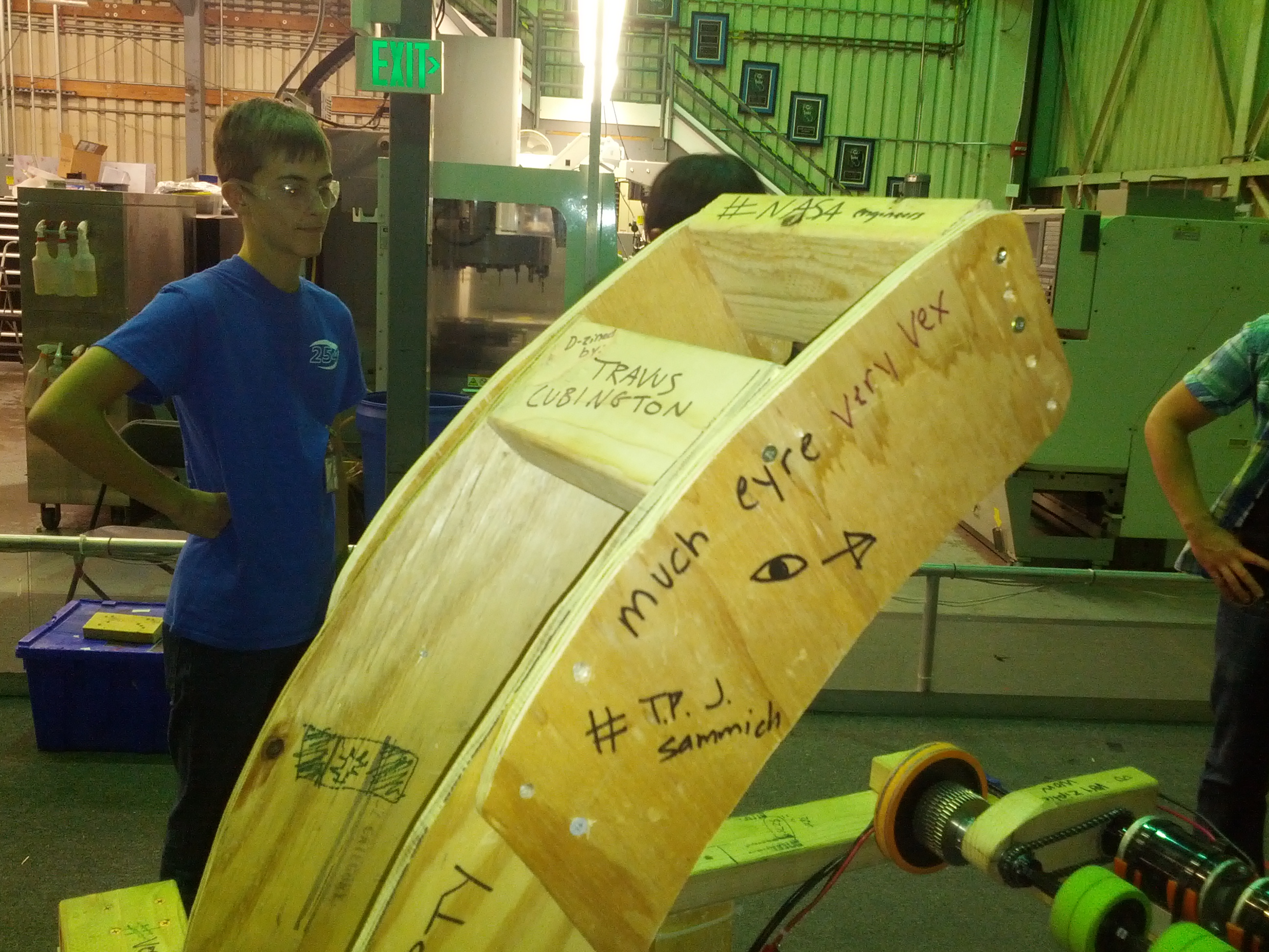
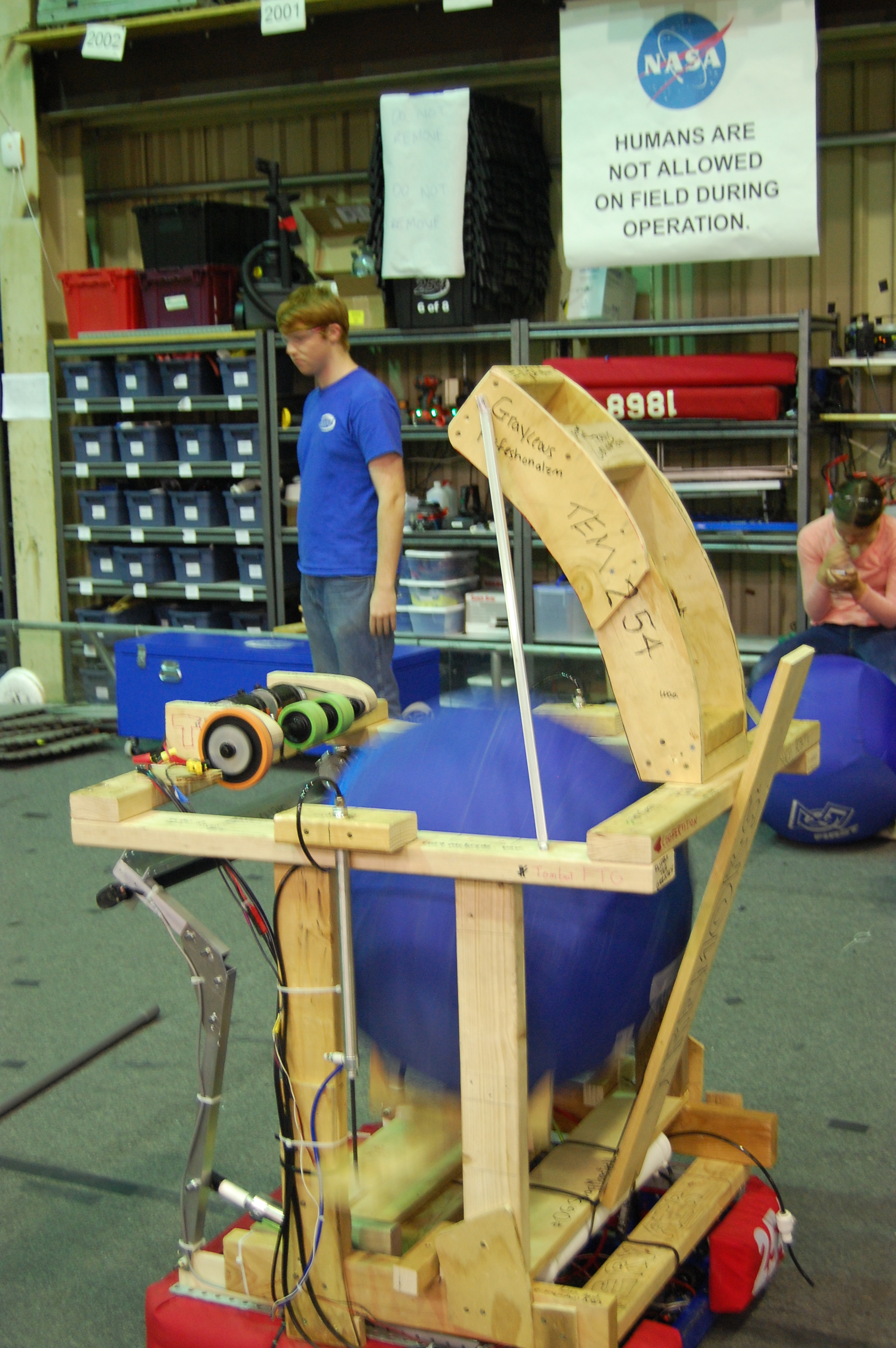
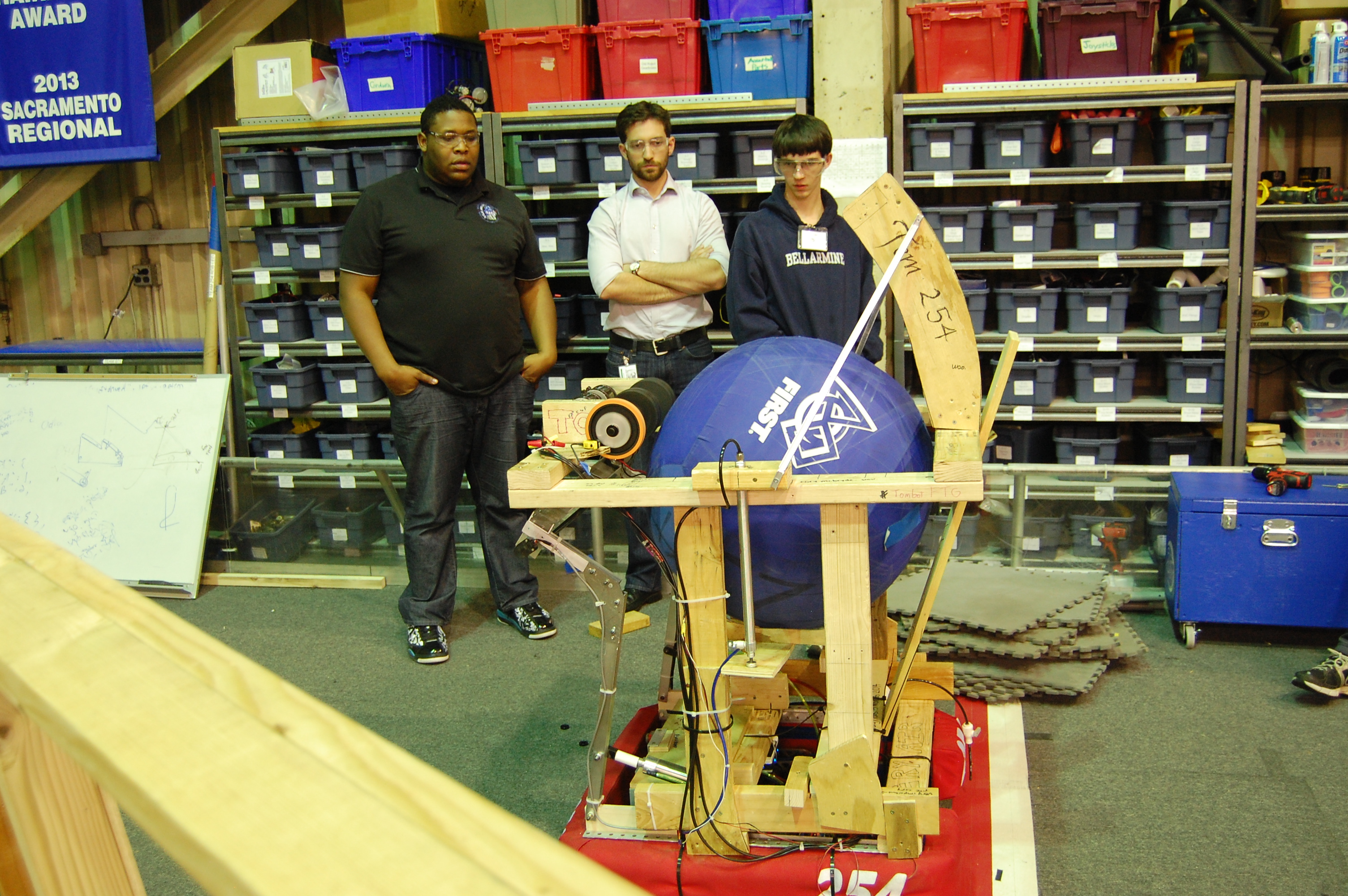
Instead of a normal blog post, have some pictures of the latest prototype (sponsored by Tem 254: Teh Chezy Pofs). As you can see, the students decorated the robot.
Day 18: Prototyping, Testing, and Programming
by Chris Powers and Jack Lee
Prototyping
Today, work continued on testing the prototype robot’s lift mechanism, which uses pneumatic pistons to lift the ball from the intake of the robot to the flywheel shooter. This lift worked successfully during most of the tests. The hopper prototype uses a V-shaped mechanism to lift the ball.
Machining
A group of students created side plates for the gearbox. After the plates were cut and deburred, they were machined on the CNC mill. All pieces for the drive base have been manufactured except for side plates.
Work began on constructing a truss for the field. Also, the wooden goal was disassembled and the official goal will soon be set up.
Programming
The programmers worked to fine tune the shooter mechanism. They created a graph of the model voltage for the shooter and compared it to the actual data with equations. This will allow compensation for the variable factors that affect the input voltage, and will increase shot accuracy.
Testing
Many students contributed to testing and refining the shooter mechanism. Many different variables were adjusted to determine the best conditions for accurate and powerful shooting. The shooter speed was varied between 4000 and 5000 rpm and the wheels for the shooter were replaced with slightly larger ones to increase flywheel energy. A banner sensor was added to measure flywheel rotational speed using retroreflective tape. The new flywheels shoot 12 vertical feet, high enough to clear the truss.
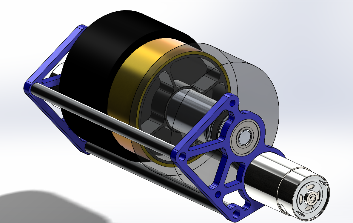
CAD
We began work on the design of a new prototype shooter. This shooter will have a sturdier hood and a lighter wheel. The hood will also have a hood extension that can be attached to replicate the two-position hood on the actual robot.
To design the shooter, students learned about moment of inertia and used SolidWorks to roughly estimate the mass and moment of inertia of the current extra weights on the shooter prototype. We used those numbers to estimate the mass and moment of inertia that we can add to the flywheel in place of the metal gears currently in place on the shooter. These numbers allowed us to model a copper tube with less mass and a similar moment of inertia which will be pressed around an aluminum hub and installed on the robot. More information on moment of inertia is available online.
Action Items
- Check the Trello
- Assemble the weldment
- Start on catcher prototype with Colin
- Test the new shooter wheel and new prototypes thoroughly with Abhi: build adjustable hood for testing shooting angles: test for shot distance for hood angles and ball pressure
- Complete CAD of bumpers, superstructure, and battery cart with Andrew and Mani
- Possibly build new flywheel weight.
Day 19: Advancing Prototypes, Prepping for Welding
by Joncarlo Avila and Brandon Wui
Prototyping
Today, we worked on prototyping an improved catcher and ball indexer. Our new catcher consists of 2 pistons that open and close the catching mechanism. We also removed the intake and shooter from the Overkill practice drivetrain for easier testing.
We made two new indexer prototypes with the goal of minimizing piston use to save air and weight. One group built a prototype that used a 6″ stroke piston to simply push the ball into the flywheels. Another group finished another variant of an indexer. This one features a 3″ stroke piston that pushes a linkage together so that it “claps” to move the ball up. The clapping indexer worked slightly better than the linear one and also uses a smaller piston. Late at night both of these prototypes were tested with the shooter and both showed consistent shots and improved accuracy over the former indexer.
Programming
Machining: Drive base
Today, we received our waterjet base plates from sponsor BAE Systems. We riveted the plates to the chassis rails which were machined over the weekend and jigged the weldment for welding. Students also worked with wire brushes to clean the aluminum oxide off of the parts to help with welding prep. The drive base is now ready to be sent out to be welded by sponsor Applied Welding Technology and will hopefully be received tomorrow so that we can prep it for power coating.
Action Items
Check the Trello!
If drive base is back from welding, prep it for powder coating.
Continue working on the indexer prototypes, testing with variable ball sizes and PSI for consistency.
Day 21: Powdercoat, Programming, and Drive base Progress
by James “Mikey” Carroll ’15
Prototyping
Today, a group of students continued to work on and improve the indexer prototype. The indexer, the mechanism used to raise balls into the flywheel shooter, features a claw-like design that lifts the ball as the two arms segments of the claw come together. Furthermore, students improved upon the previous indexer design, which included one piston and two gears, by adding a second piston (one for each claw arm). The intentions of this design are to improve strength and allow each arm to move independently, thereby increasing ball stability and raising accuracy.
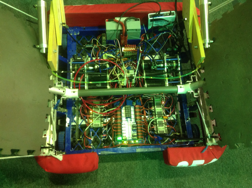
Manufacturing
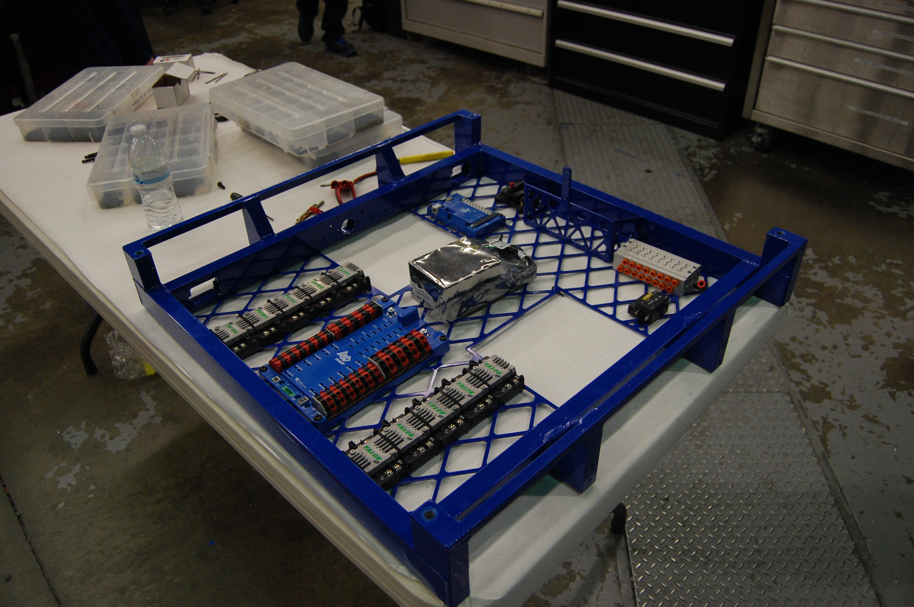
Students began to construct the drive base chassis for the finalized robot. First, students drilled and tapped holes in the chassis, then installed hardware and electronics into the base plate, in particular the main switch, the power distribution board, the digital sidecar, and the Talon motor controllers. Students are beginning wiring.
Programming
Work continued on designing and fine tuning the code for the robot data logger. This log includes information directly from the robot’s sensors, such as drive speed or intake speed. The log also provides easy visualization of all movements of the robot and quickly reveals issues with the robot, such as one motor running faster than another, in real time. Students will also use the information from this program to tune PID.
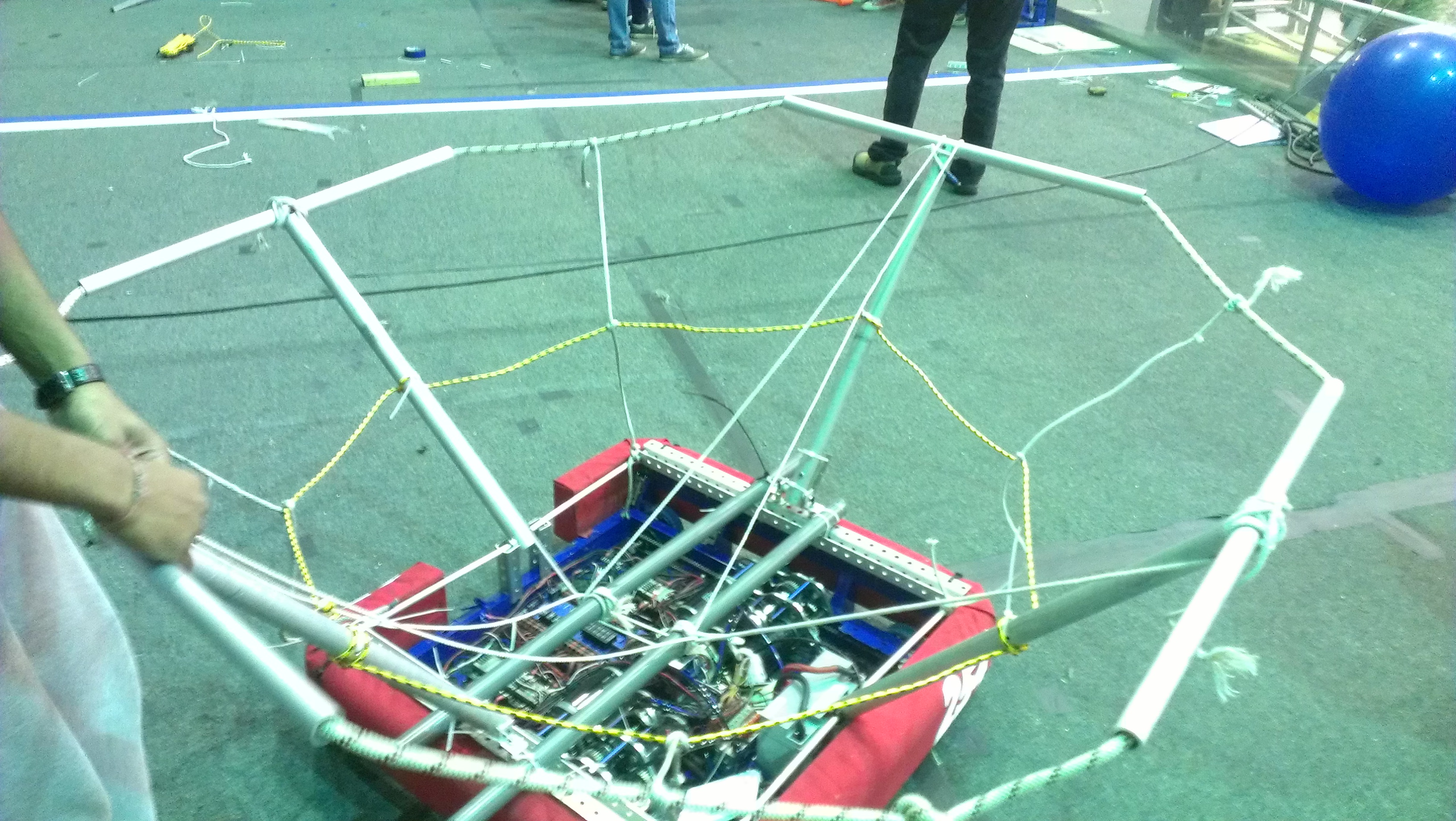
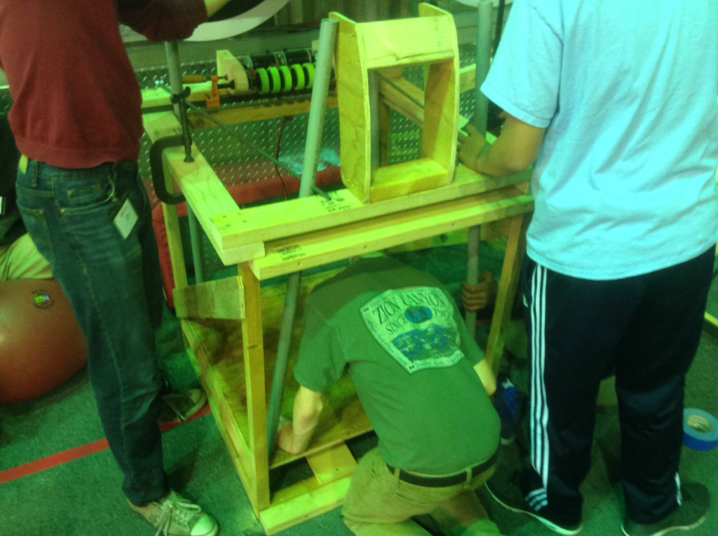
Field Construction
Work continued on the construction of the truss for the field. Students completed a CAD design for the truss.
Chairman’s Award Submission
Students resumed work on Team 254’s Chairman’s Award submission, making lots of progress on the executive summary portion and the essay portion of the entry. Work continued toward a finalized thesis for the essay portion
Action Items
- Add 4 gauge wire to both robots (Contact Mani Gnanavisam if interested)
- Connect Talon motors to PDB and digital side car (Contact Mani Gnanavisam if interested)
- Finish construction of the truss (Contact Mani Gnanavisam if interested)
- Put a backing on the shelf (Contact Mani Gnanavisam if interested)
- Check the Trello (Contact Abhi Kumar if interested)
