
Posts Tagged ‘ FRC ’
FRC Day 4 Build Blog
Day 4: Iteration of Prototypes
Prototyping
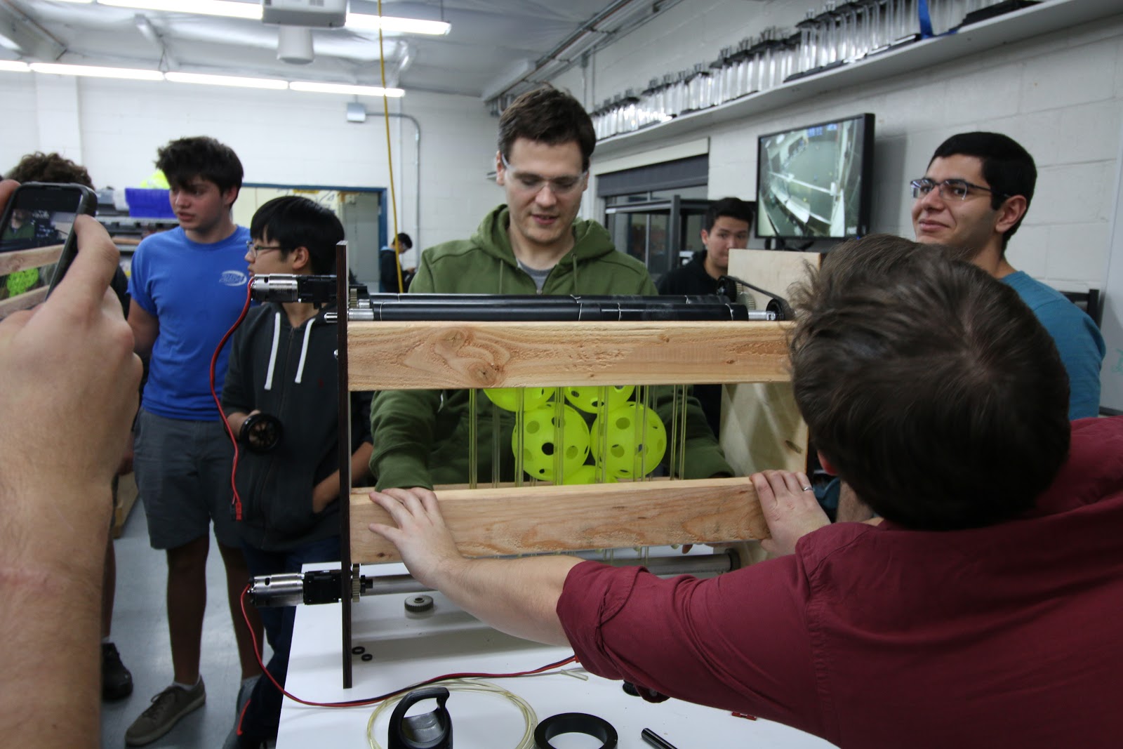
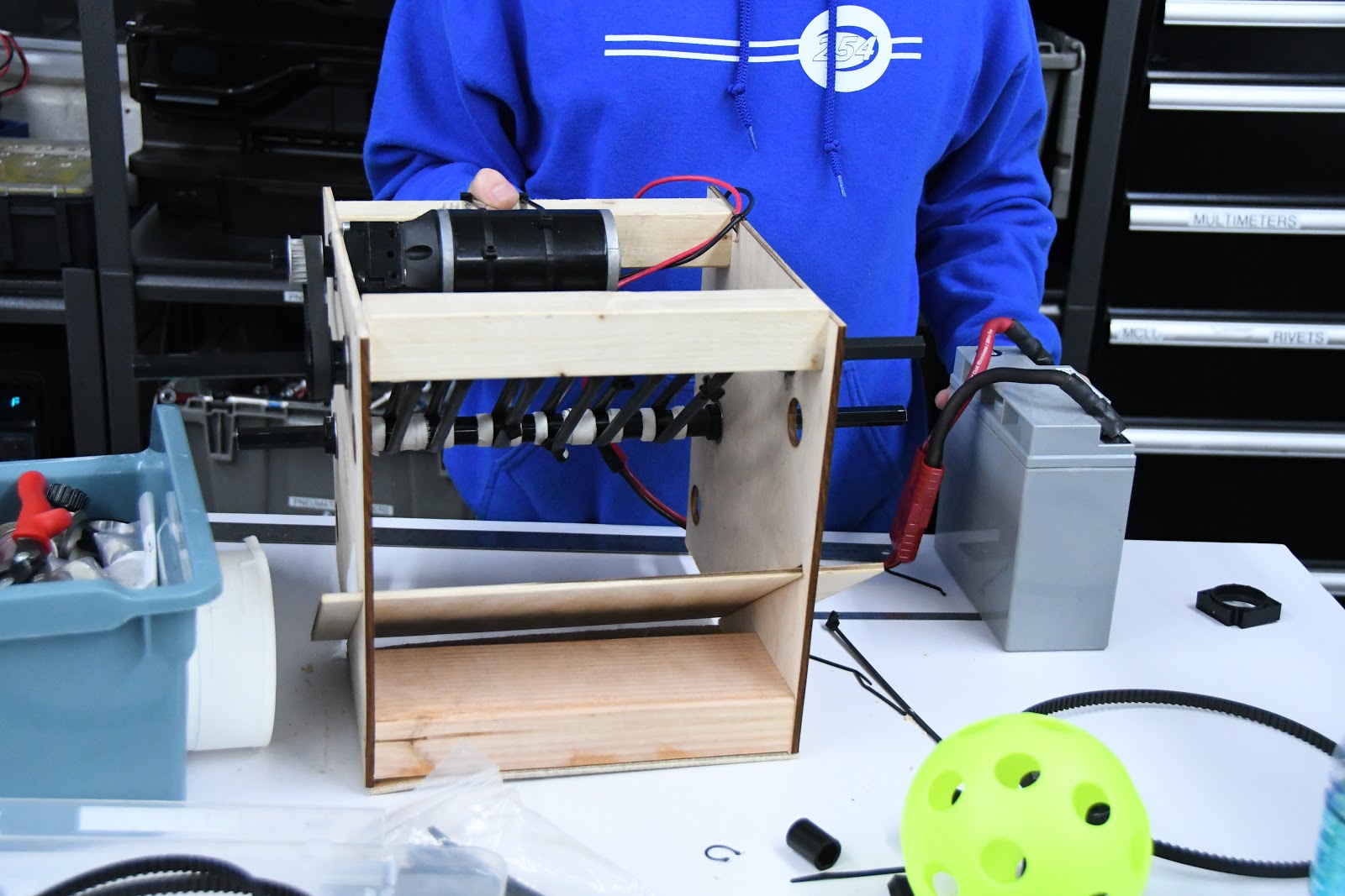
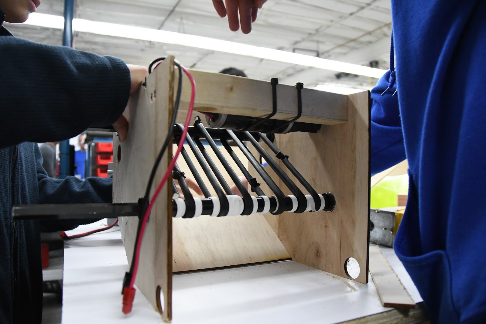
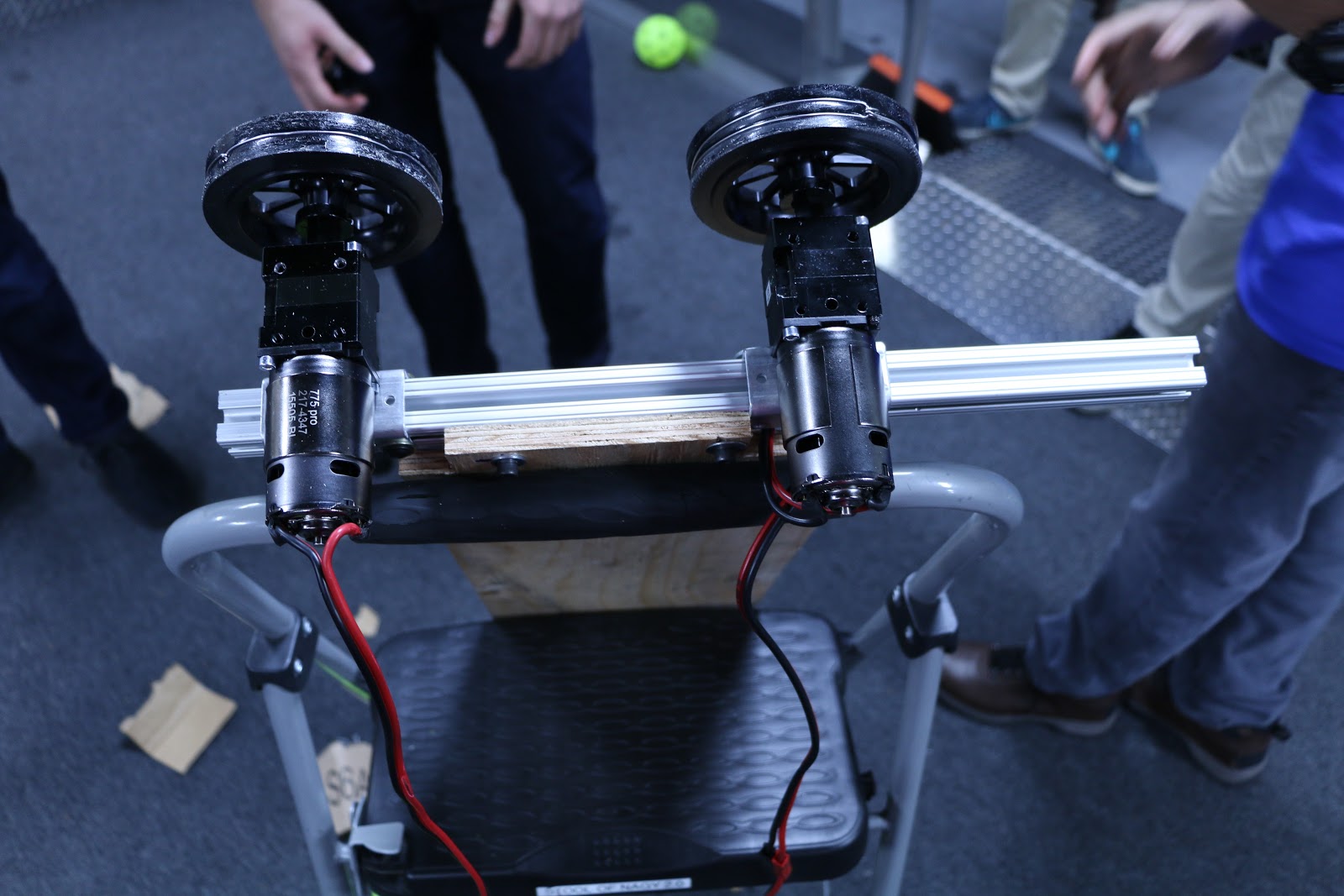
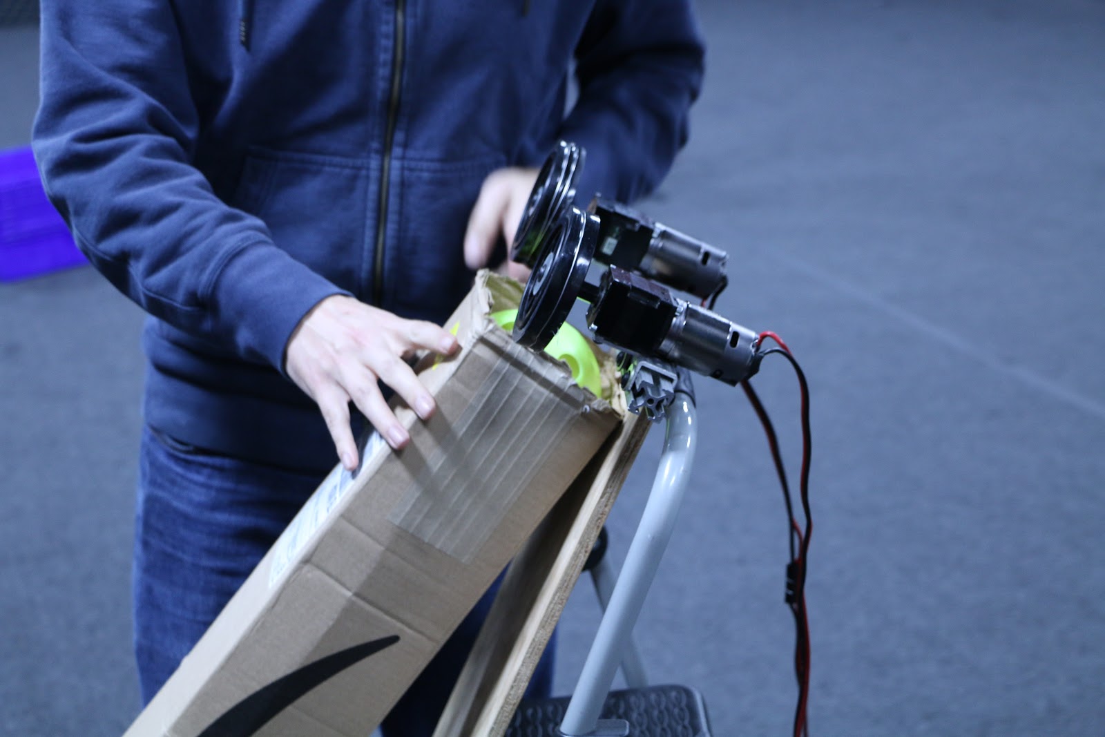
Double Wheel Vertical Flywheel
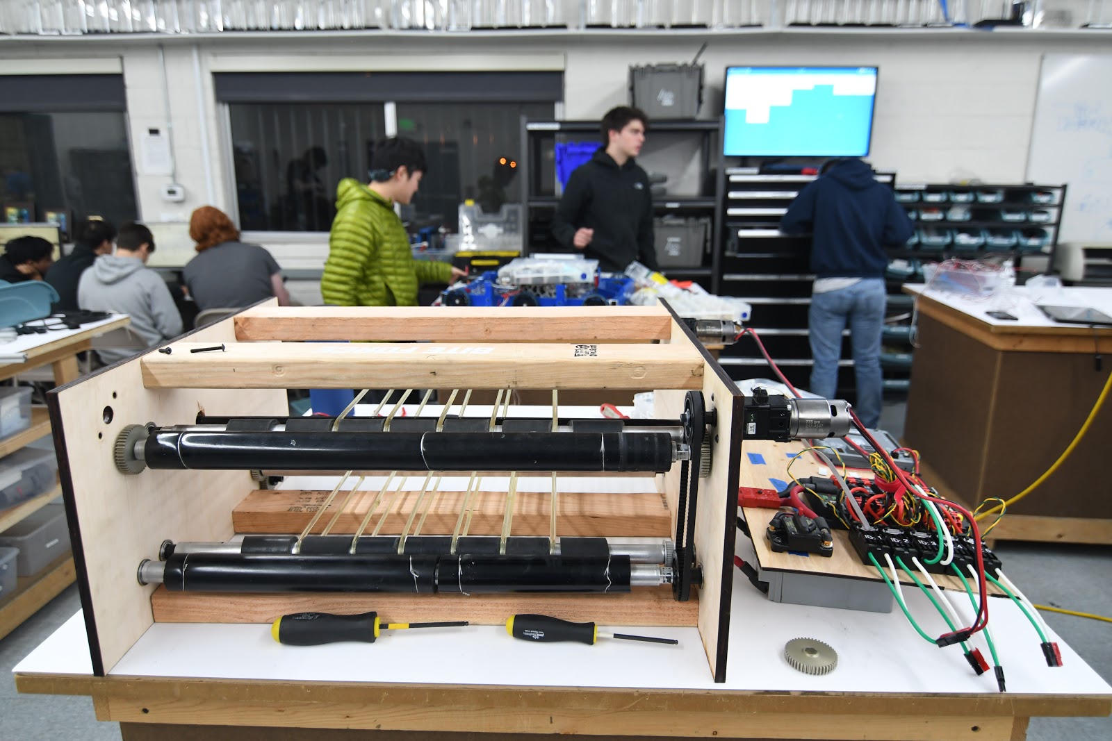
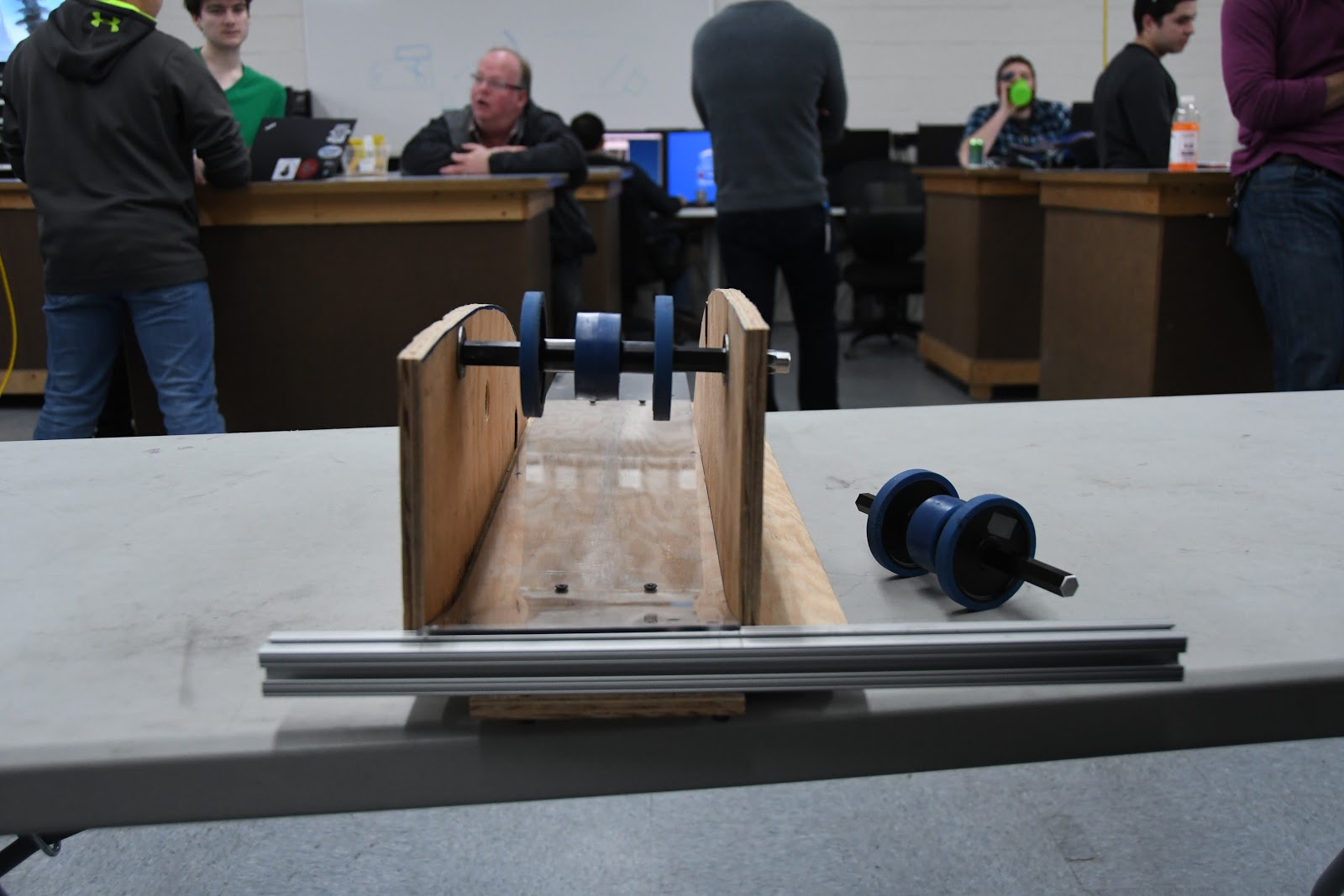
As we proved this flywheel could attain a high throughput, we transitioned today to begin testing different wheel types and compression as well as the conveyor system. In the process of setting up the next prototype, we found we lacked enough polycord pulleys, and machined more out of some delrin stock. We scavenged the 3:1 VersaPlanetary gearboxes from our previous prototype. While we did not have enough time to finish developing the prototype, we have all of the pieces and can finish it quickly tomorrow.
Fuel Intake
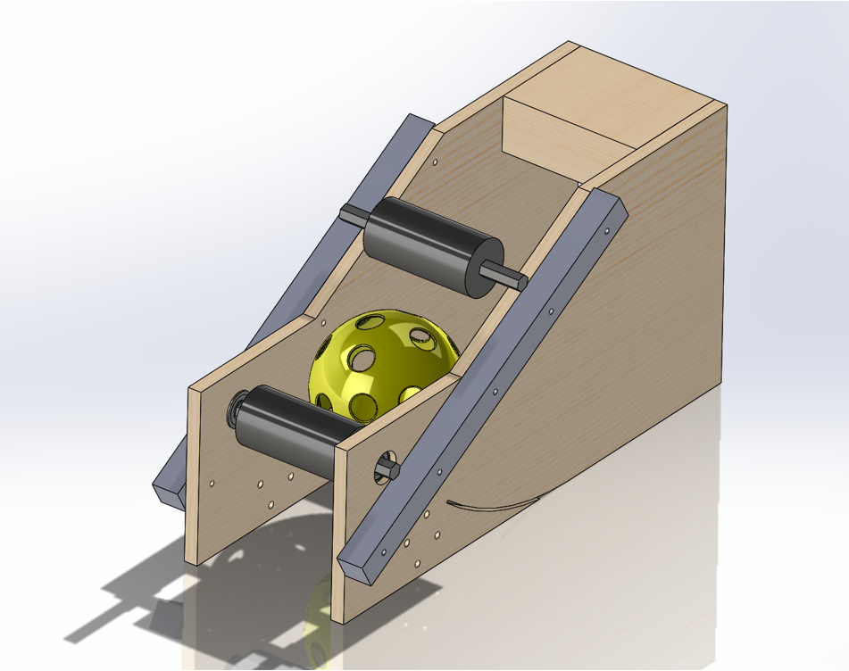
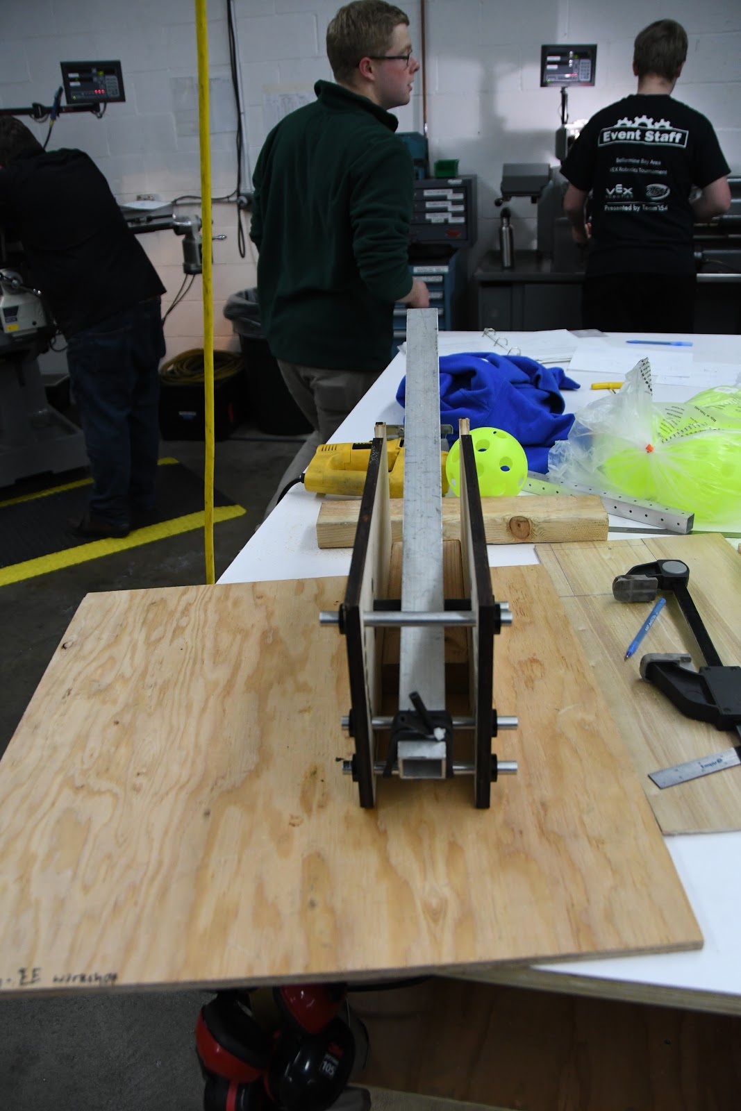
Taking the intake design from yesterday using two polyurethane rollers, we laser cut and assembled it, discovering that while it was able to pull balls up and over the bumper, the balls sometimes got stuck. the compression was too little on top of the bumper and it sometimes got stuck. The compression seemed to be too little at the top of the bumper because we didn't account for the bumper compressing alongside the ball, so we went back in CAD and redesigned the geometry of the upper roller to have increased compression. We are still in the assembly stage of the new and improved version, so we will see tomorrow how well it works with the improvements. For the future, we still have to see how effective the new design is before we CAD the real intake for the robot, but it is likely that this will be the preferred design because of the simplicity of having just 2 rollers.

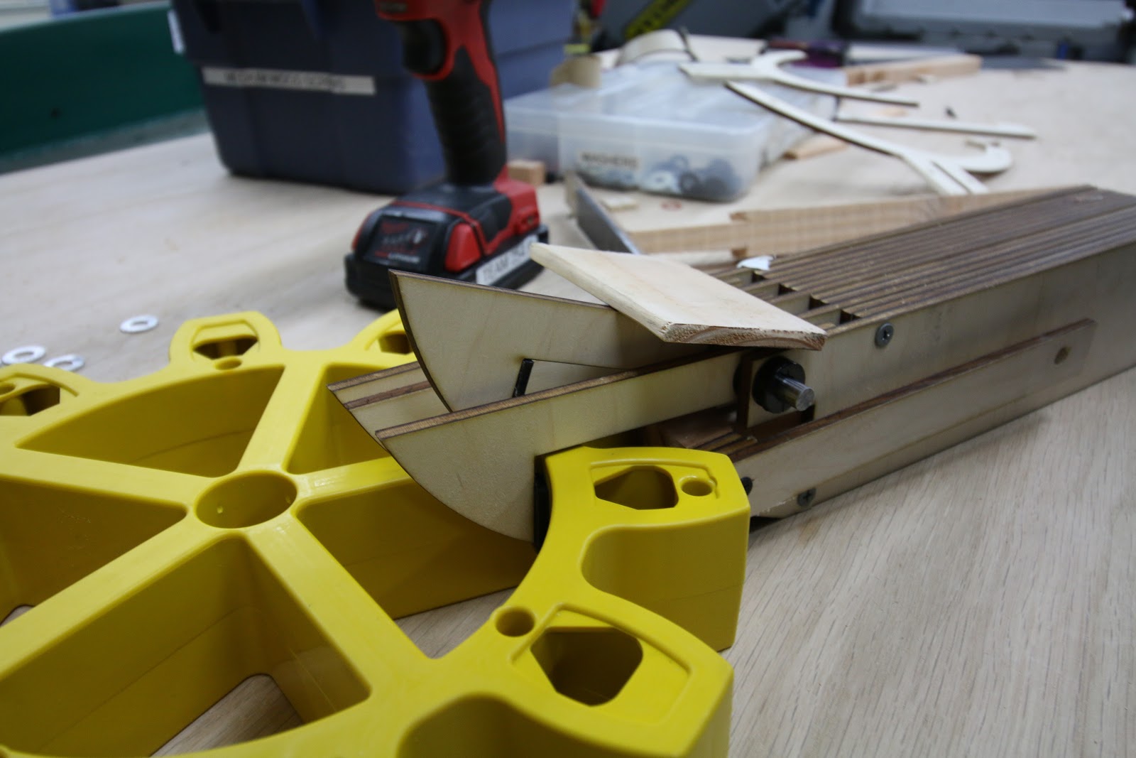
Gear Intake
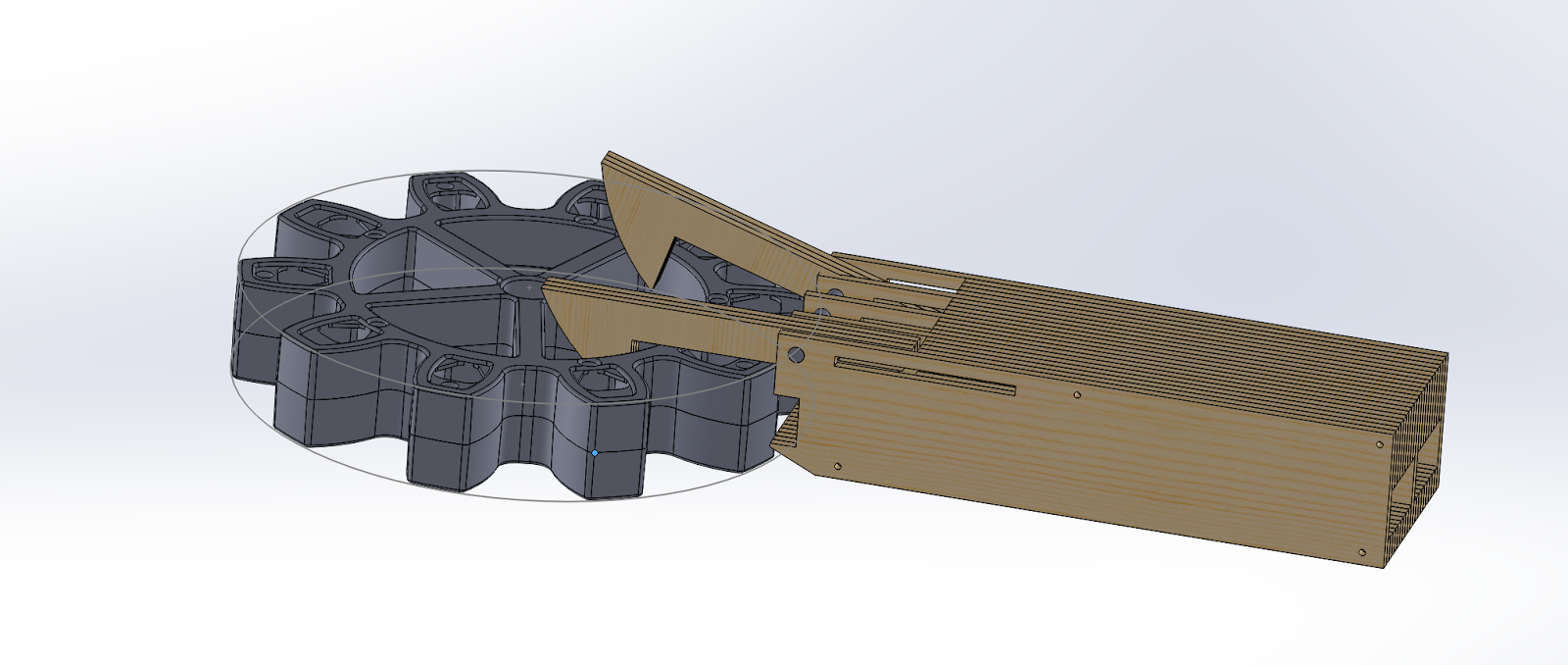
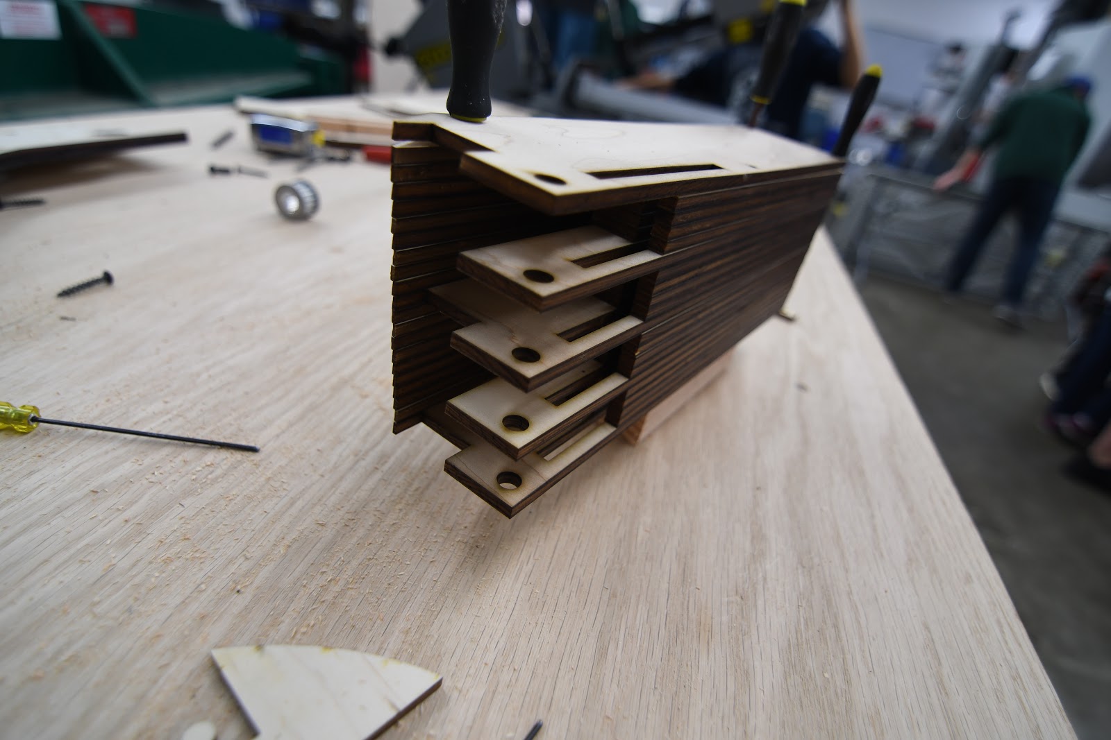
Throughout the course of the build today, we worked on constructing the 3D CAD design that one of the students made the day before. This worked out well because we were able to get the whole thing laser cut and fully constructed relatively quickly. Although this design seemed to be very similar to the previous version, a new key feature was added: A locking system for the claws while they are grabbing onto the gear. Although we were not able to fully test the design today, these improvements should theoretically allow us to manipulate the gear in 360 degrees, something we were not able to do previously. At the build tomorrow (Saturday), the main focus will be to finish building the prototype and look at potential ways of packaging the design give the tremendous size constraints presented.
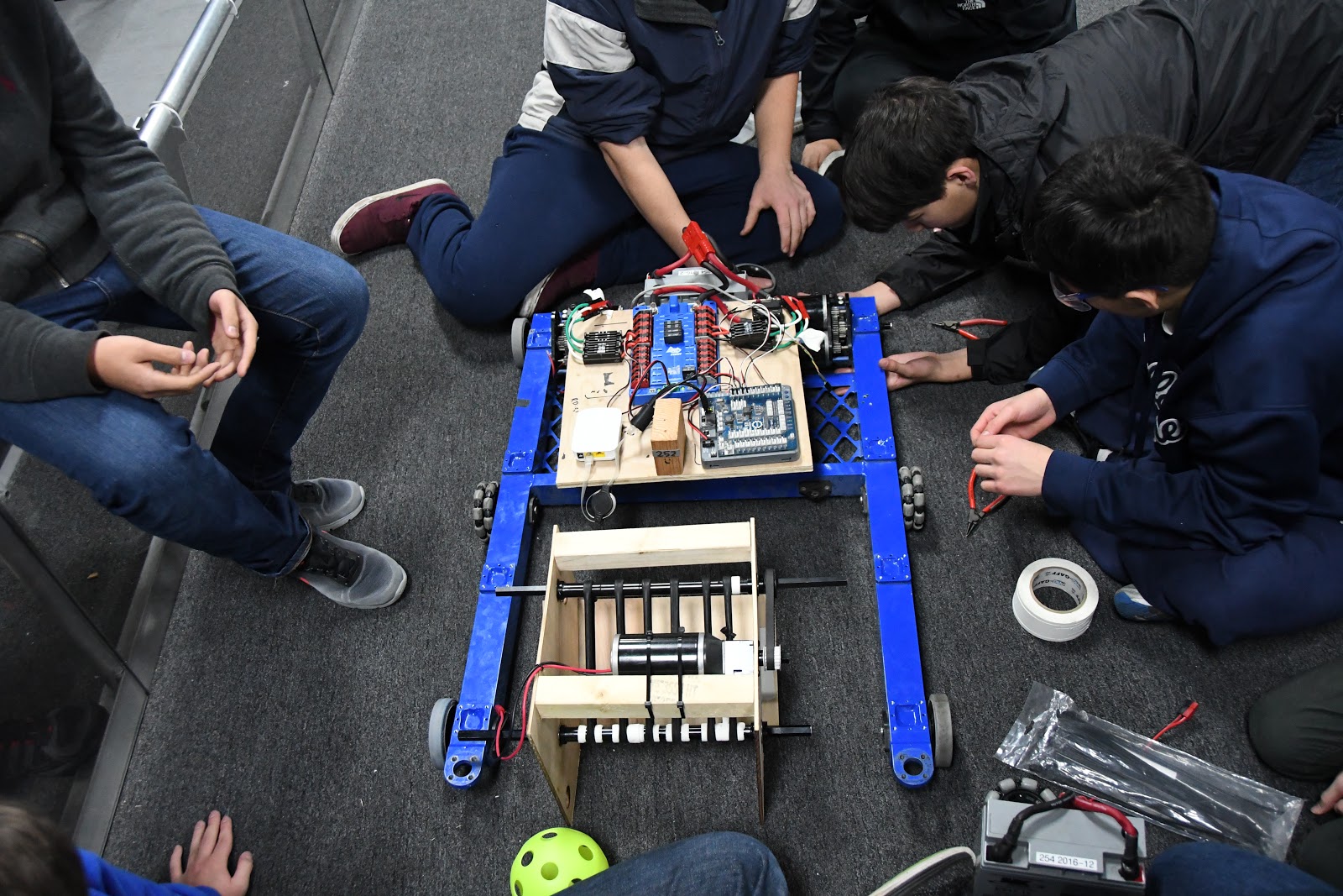
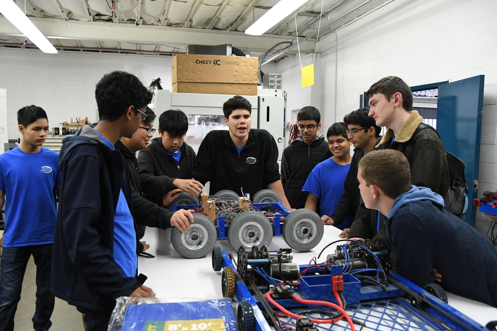
Drivebase
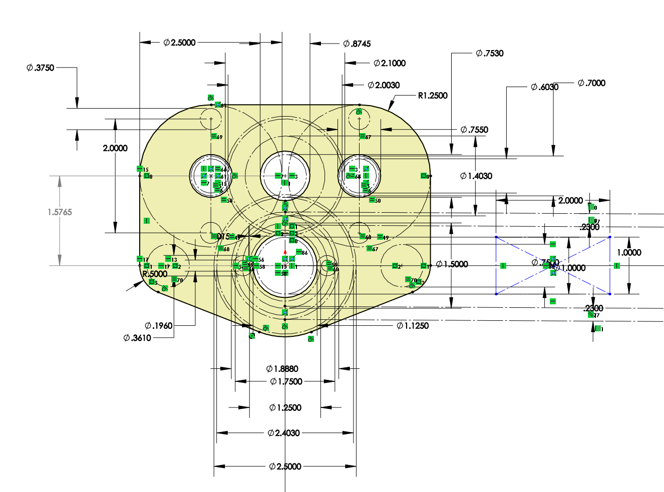
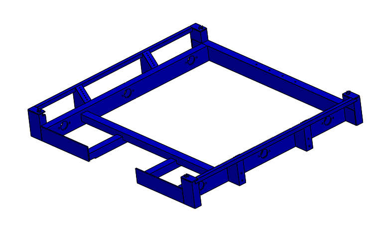
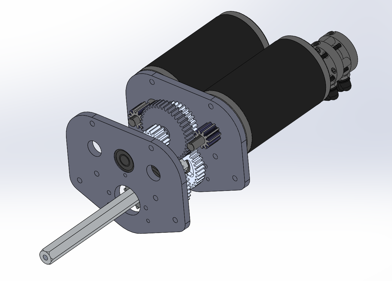
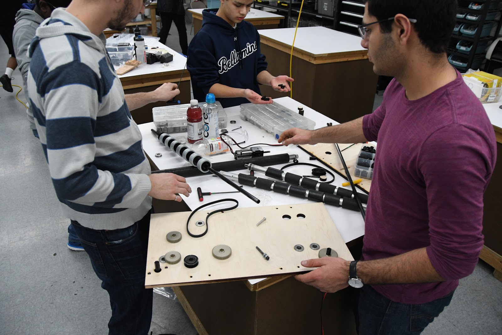
Today we finalized the CAD Design for the Drive Gearbox, which is now almost ready for manufacturing. We started by pocketing the gearbox plates, a method used to reduce weight while maintaining the structural integrity of each plate. Our two gear ratios are 15:48 and 28:35. We decided to have a two stage gearbox with a dog shifter in anticipation of heavy defense, allowing the robot to have speed and maneuverability based on the situation. We also added spacers, an intermediate shaft, and designed a new front gearbox plate. Through the design of the gearbox plate, we were able to save 0.04 pounds in a game where the robot weight is inversely proportional to its speed.

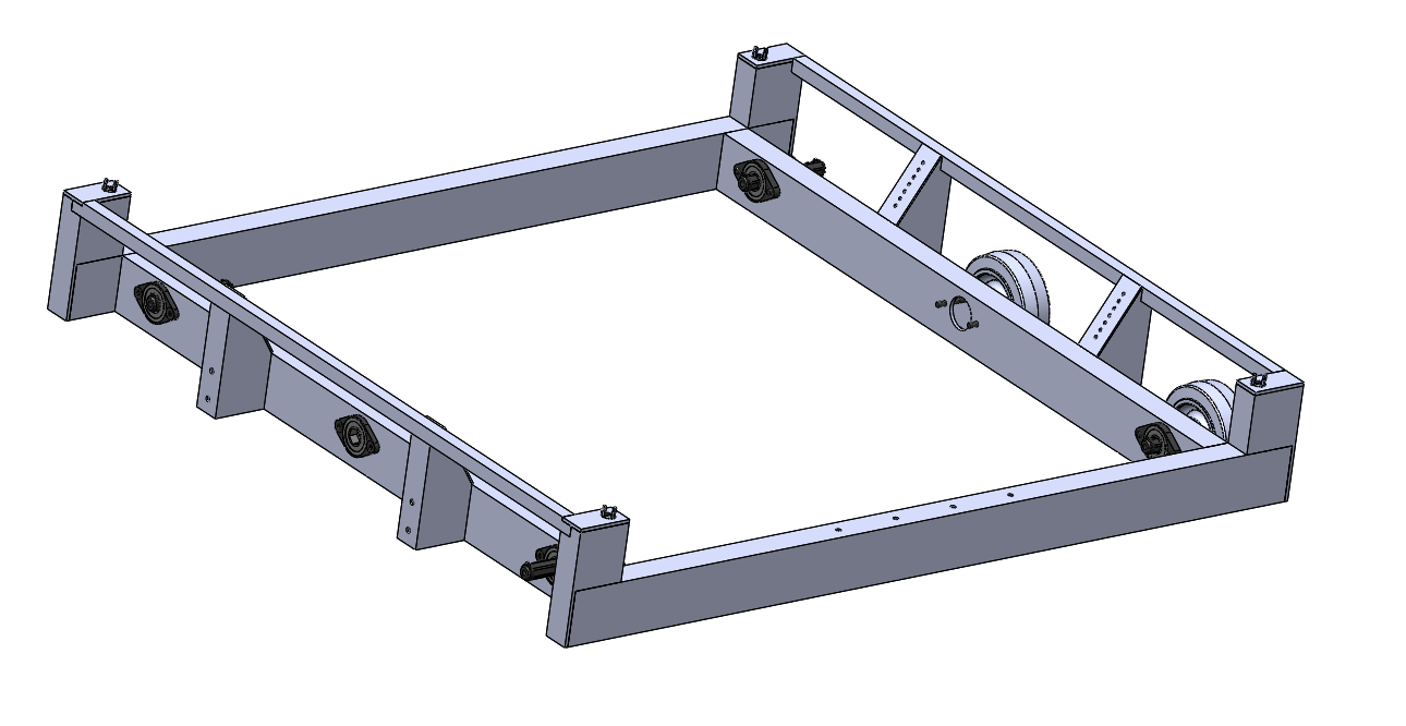
Regarding the drivebase weldment, We modified it to have a cut out in the back. The gearboxes will sit in the two cutouts in the back corners and the gap in the middle will be for a gear intake mechanism..
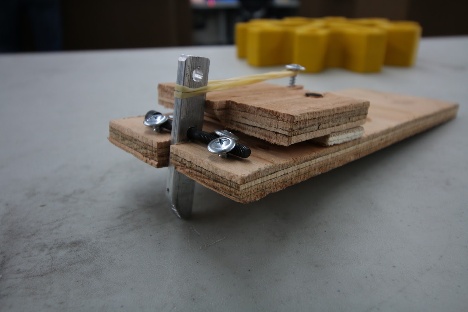
Climber
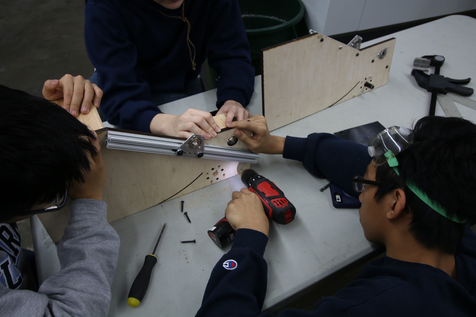
Today, the rope-climbing project finished prototyping a “comb” to grab the rope as well as housing to connect the comb to the robot for testing. We completed the comb by measuring the diameter of the string to find the distance between each prong of the comb. After this, we cut these parts out and tested it by ensuring that rope with knots would successfully hook onto the comb. Besides this, we also created the housing by attaching a VersaPlanetary enabled motor to a wood structure. We then connected the motor to a shaft by using gears and bearings. At this point, we just need to attach the comb to the shaft in order to finish assembly and begin testing.
Programming
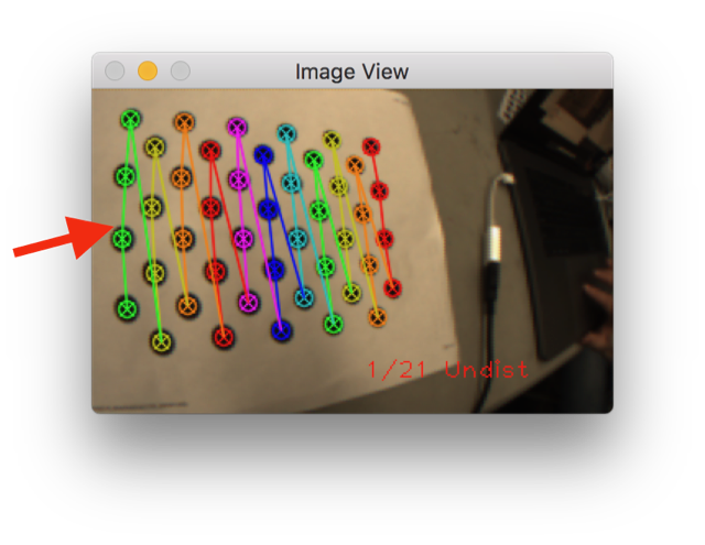
Camera Calibration:
After manually calibrating one camera with limited success, we decided to automate the process to make calibration quicker and more accurate. The goal of the project is to have the OpenCV calibration code to read the camera input automatically so that we can see what angles will work for calibration before we take the picture. Today we downloaded all the necessary software needed to run the calibration program (OpenCV, Eclipse C/C++, MinGW, etc.); however, we did not finish this. Needed for next build is to set up Eclipse with a compiler and Download all the premade libraries for OpenCV. After that, we can edit the code to make it more user friendly, by having it connect directly to the Pixy Camera, and improve calibration.
Camera Connectivity:
Today, we deployed multiple test programs to an old RoboRIO to test our serial driver. Unfortunately, we ran into many issues early on. We then created another program to dump raw SPI input data to attempt to diagnose the issue: we noticed that we were only receiving null bytes (0x00), perhaps due to an SPI protocol error. We found that this occurred because the SPI connection hardware had a loose contact issue between the RoboRIO’s pins and the header pinout; after this was fixed, we received (0xff) bytes. Unfortunately, even after attempting to replicate the protocol according to the description, we could not get the PixyCam to send us anything other than (0xff), which was oddly not documented in the protocol information page. However, we suspected that the issue may stem from WPILib’s abstraction of the SPI interface itself; thus, we plan to implement a PixyCam SPI driver in C/C++ based on a low level library that accesses the serial port directly. In addition to working on SPI, we also worked on our `libpixyusb` interface, attempting to run the sample program. Unfortunately, we received an error about a failure to transmit/receive data over USB; we traced down the issue in the libpixyusb source code to the low level USB handshake. Getting `libpixyusb` to work reliably on the RoboRIO will likely be extremely difficult, possibly even requiring custom drivers and a kernel patch; the exact same code works as expected on an Intel x86 laptop, but when cross-compiled onto a RoboRIO with the FRC C/C++ toolchain, it encounters this unexpected error. After evaluating the pros and cons of both methods of connectivity, we decided to continue to pursue SPI rather than USB.
Robot Programming
Last workday, we tried deploying robot code to the RoboRIO but ran into problems deploying the code due to conflicting libraries for the CAN Talon motor controllers. After removing the conflicting drivers, we were able to successfully deploy the robot code. These changes are reflected in the latest commit on Github.
We then successfully deployed the code for the shooter prototype to the RoboRIO, but faced problems with maintaining a constant RPM. We used a basic feed-forward controller, which should set a near-constant RPM, but we measured drastic fluctuations in the RPM. We hypothesize that this is because the encoder is returning data at a different rate than the robot is running, leading to discrepancies in the measured RPM. To fix this, we will try connecting the encoder directly to the RoboRIO’s digital inputs instead of to the CAN Talon.
Waypoint visualizer:
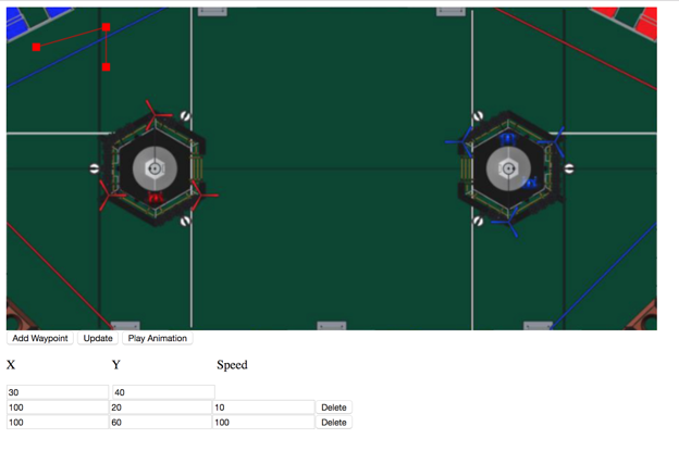
We worked on an autonomous mode path simulator. The app lets a user enter waypoints and speeds and plots out a path that the robot will take. The app also supports animating the robot's movement. We also worked on implementing a radius feature into the program that would allow the robot to round corners. This app is a vast improvement over the current method of programming paths which require trial and error. With a helpful web interface, we will be better equipped to plan auto routines before we even test them, which allows us to develop before the robot is built. It’s not done yet, but we have made a lot of progress:
FRC Day 3 Build Blog
Day 3: Progress in Prototypes
Prototyping
Double Wheel Vertical Flywheel
Today, we worked on assembling the Double Wheel Vertical Flywheel. Taking the parts from last build, we assembled it using the new VersaPlanetary gearboxes and encoders we received. We assembled the flywheel to our previous spec, but we had problems with the gears we had in stock. We changed the ratio in CAD and laser cut a new plate. After doing so, we assembled the flywheel. While the flywheel worked well after changing to polyurethane, the conveyor system failed. Rather than cutting a new plate, we cut a bearing hole and inserted a hex shaft on the inside of the polycord, essentially acting as a tensioner. This worked relatively well, but needs further refinement. We did prove our concept, and will further iterate to better understand how best to integrate our design with the robot.
Testing:
For the Double Wheel Variable Compression Vertical Flywheel, we assembled the majority of the pieces and only need to insert the wheels to begin testing.
Fuel Intake
We finished assembly and began testing the belt intake, which was very fast when pulling balls in, but protruded several inches beyond the bumper. We began to design a new intake today, which will be much more compact and will therefore allow for a larger hopper and more room for other systems. This intake uses no belts, and two polyurethane rollers pull the balls up and over the bumper into the hopper. This removes the inefficiency and added complexity of belts, and makes the whole design cleaner and simpler. The intake's design is finished in CAD, but it has not been built or tested yet. On Friday we will laser cut it, finish assembly, and test it to see how effective it it..
Testing:
Gear Intake
The Gear Intake development process continued today with the construction of a recently CADed design that has an inner slider in order to pinch the gear between the claws and itself. This process was difficult because the .25” plyowood that was used for construction is actually .2”, so the original design needed to be modified slightly so that all the pieces would fit together. Other small improvements involved adding polyurethane strips to the inner slider and the claw so that the whole system grips onto the gear well.
Testing:
Drivebase
We finished an initial weldment of the general structure modeled after our 2014 robot and the side rails/bearings/housings modeled after our 2016 robot. Taking bumpers and an intake into account, the frame was dimensioned to fit within the 36" by 40" by 24” size limit.
In addition, we designed the drive train gearbox in CAD with 2 CIM motors per side in a 2 stage reduction with a dog shifter and pancake piston to have 2 speeds: low gear for pushing force and high gear for maneuverability. With the design almost done, we only have to add spacers, intermediate shaft, standoffs, screws and nuts, retaining screws, and pocketing to the CAD (members can access the design from pdm under the name 254-17-A-0300 Gearbox if you want to see or help design it).
Climber
Today, we designed and began to build prototype mechanisms for climbing the rope. The prototypes for actually holding onto the rope included variations combs with differing spacing. We began working on a standard mount for each type of prototype climbing roller. We decided to use a VersaPlanetary gearbox in our build, using a gear ratio of 1:90 to heavily reduce the rpm of the motors from ~18,000 RPM and increase torque to ensure the robot could lift itself. We then assembled the multi-stage gearbox, attached the motor, and soldered the battery leads. Lastly, we began the process of building a frame and prepared the parts to completely assemble the mounts next build.
Programming
Control Board
On Wednesday, we met up and worked on control systems for recent prototypes and we also continued developing pixycam communication. We added three talons to the prototype board to support the growing complexity of prototypes.
Robot Programming
With a prototype board ready, we added feed-forward PID control to our two-roller shooter prototype. PID is a control loop that keeps a constant motor speed, allowing us to effectively test the shooter prototype.
We also rewrote a majority of our code using elements from last year’s code, to avoid re-inventing the wheel. The new code is far more scalable and efficient. In particular, we implemented Loopers, a structure that runs code extremely fast, and compartmentalized our code into the various (potential) subsystems on the robot. We also discussed code conventions to ensure uniformity in the code down the road.
However, we had issues with compiling and deploying the code due to issues with the motor controller driver. We’re resolving those issues down the road.
Camera Connectivity
We worked on camera connectivity, finishing a testable version of an SPI driver built on WPILib for the RoboRIO. Previously, we built a native library that allowed us to communicate with the PixyCam over USB and wrote a JNI wrapper to let us invoke the native code from Java, but today we encountered issues when connecting to a physical PixyCam. Rather than debugging the USB connection, we decided to ensure that we could build a reliable SPI driver first, as we are confident that we will be able to communicate with the camera over SPI. Though a USB interface would be optimal, it is significantly complex and we plan to work on that functionality once the SPI driver is confirmed to work as expected.. We added a new pinout to the PixyCam and connected it to an old RoboRIO board for testing. To help with testing, we connected the PixyCam to a computer and trained it to recognize the yellow game balls. In the upcoming builds, we will proceed with testing our SPI driver with an old RoboRIO so we have a working method of connection for this year’s code.
FRC Day 2 Build Blog
Day 2: Prototyping
Today, we continued our work on prototyping designs for the shooter, intake, and drivebase. Our programming team also worked through a variety of projects including camera calibration and configuring the RoboRIOS.
Shooters
Double Wheel Horizontal Flywheel
We assembled the feeder for the horizontal flywheel shooter using three wheels of two different sizes to optimize contact with fuel balls. We determined that we would either use polycord or rollers for the feeder. However, due to availability of resources, however, we decided to prototype with a wheel roller. The horizontal flywheel was ready for testing but is still waiting on more planetary gearboxes.
Double Wheel Vertical Flywheel
Today we continued working on developing a double wheel vertical flywheel. In the process, we tried to optimize throughput with the limited space available on the robot. Initially starting with a hand loaded prototype, we combined the shooter with a conveyor prototype to remove the variables of human error.. We managed to design and laser cut the sidepanels for the prototype, and began assembly. We have organized the VEX Pro VersaPlanetary gearboxes and will implement it on Wednesday.
Another project based off a double wheel vertical flywheel aimed to optimize the best materials and fuel compression to maximize accuracy and shot speed. We spent the build designing a model in Solidworks to later be laser cut.. By the end of build, we acquired all the materials for the prototype including the 80/20 Extrusion Material, T-nuts, modified Versa Side Bearing Motor Gussets, 2 x 4 Wood Blocks, Bearings, and laser cut to design ½” Plywood.
Catapult
We improved the catapult and eventually hit an accuracy rate of 15/15 into the high goal. The improvements we made include:
-
Adding a stronger shaft
-
Tightening the medical tubing that provided the power to pull the shaft to the hard stop
-
Moving the hard stop and axle into the optimal position
-
Figuring out how to calibrate the machine
-
Securing the catapult to a piece of plywood so it wouldn’t move after every shot.
The design still needs a lot of improvements based on the power applied and the contact with the ball to make it into the boiler quickly and consistently.
Testing:
Intake
Today we took the intake prototype from yesterday and added several more surgical tubing belts in order to pull in more balls at once. In addition, we resized it for better geometry and added a CIM motor for lots of power. The results are very successful, and we are able to rapidly suck in several balls at once over a bumper, meeting our original goal for this prototype. The next step is to mount it on our practice drivebase and see how well it can intake once in a robot. We prototyped this specific intake because we have used similar ones in the past successfully, but were unsure how they would react to the plastic balls compared to more traditional foam balls.
Testing:
Drivebase
Today for the 2015 Deadlift drivebase we installed a new radio with updated 2017 firmware in order to successfully connect to the driver station. Additionally we experimented with different types of wheels. Initially we started with colson wheels on the outside and an omni-wheel for turning. The idea was that due to the center drop of the drivebase we would only be on an omni, and a colson wheel at all times. In order to optimize for turning we changed to all omni wheels, yet the turning was erratic so we think another set of wheels would be best for this game.
Gear Intake
Today we worked on the gear intake for the 2017 FRC Robot. The process involved spending a little bit of time on CAD to create a preliminary design, and then following up by actually laser cutting the wood pieces and then putting them all together. After that, we experimented with different heights for the grabber pieces on the claw to figure out which angle would be optimal in sliding up and over the edge of the gear. The next step in this project will be to cad a significantly more robust version of a similar design, as well as add a system for actually “grabbing on” to the gear so that we can manipulate it.
Testing:
Programming
A lot got done in programming today! We had our first build meeting and we will be having subsequent meetings every build where we will get anyone involved who wants to work on something. During this build we divided the work into the following tasks:
-
Installing updates onto drivers stations
-
Camera USB to RoboRIO Communication
-
Camera Calibration
-
Programming prototype boards
Driver Stations
We successfully updated the driver station software on the driver station computers. Now, everything works well.
Camera USB to RoboRIO Communication
Since last build, we successfully cross-compiled libpixyusb to the RoboRIO’s ARM architecture using QEMU on Ubuntu. We then created a JNI for it so that we can integrate it into our codebase. However, it has not been tested yet and we will be doing this throughout the week. If his port works, then we will not be using SPI with the Pixy Camera
Camera Calibration
The goal of calibration is to get rid of the distortion in the camera. Here are some screenshots that illustrate this distortion:
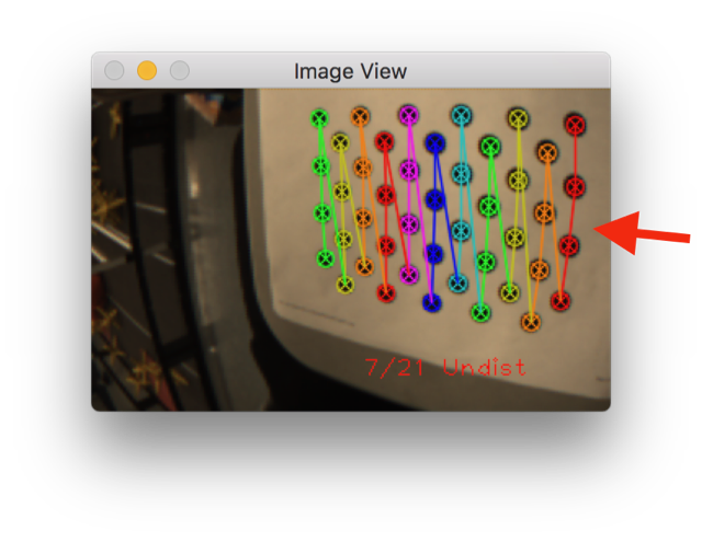
After the calibration, the dots in the image or more linear and the edges of the dot grids are parallel. This is the result of the calibration:
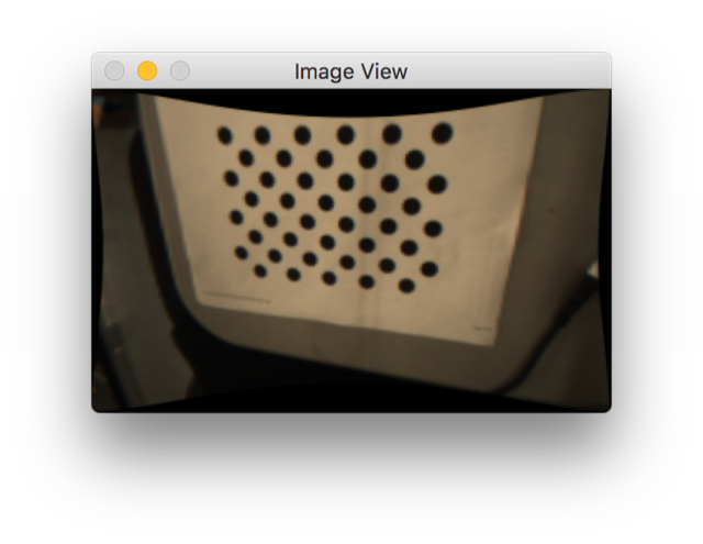
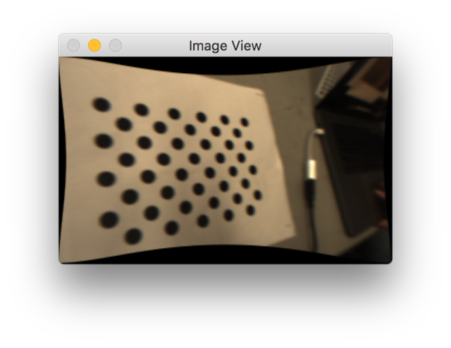
With better calibration, we will be able to more accurately approximate the angles of the goals so that we can make the targets. The calibration above isn’t perfect, but we are still working on making it better. The current issues that we have encountered are mostly due to the low resolution of the pixy camera which prevents OpenCV from recognizing the dots at more oblique capture angles. If it were higher resolution, it would generate a more accurate calibration.
Robot Programming
This build, we successfully configured the RoboRIOs and programming computers to use the latest version of FRC software, albeit with a few hiccups. In techno-speak, the RoboRIO wasn't assigning itself a static IP address, leading to communications problems. The programming subteam was able to overcome this issue, albeit with a temporary fix.
FRC Day 1 Build Blog
Day 1: Kickoff & Testing
Today was the first day of the FRC build season. The new game, FIRST Steamworks, was revealed, and we began evaluating strategies and testing prototype mechanisms for our 2017 robot.
Helpful Links
The game manual and rules are linked below. All team members should familiarize themselves with the manual, especially the Match, Game and Robot sections.
Game animation:
Prioritization & Strategy
To evaluate potential strategies for our team, we estimated times to perform tasks such as picking up and depositing gears, collecting balls, hitting hoppers, etc. We then compared that time to the point value of each task to determine a priority list of items to prototype as well as to begin match strategy.
For 2 strong robots working together in eliminations, an optimal strategy could be to each perform a 2 gear autonomous and then in teleop do 2 “hybrid cycles” in which they each score both a round of 100 balls and a gear followed by 2 “ball cycles” where they score only balls. This would produce a maximum score (assuming 80% shot accuracy) of 410 points. Perhaps the third robot could play defense rather than contributing offensive points.
More information on this strategic analysis can be found in this spreadsheet.
Prototyping
Today, we started by prototyping various mechanisms to accomplish each of the tasks in the game. Later, we will work to evaluate the prototypes, determine which are most promising, and integrate them together for more comprehensive testing.
Shooters
High Throughput Shooter –
We discussed creating a shooter which can shoot a large number of balls very quickly (goal is 50 in 1 second). This will need to be designed, built, and tested in the coming week.
Single Wheel Vertical Flywheel – back spin –
We made a prototype for the vertical flywheel by modifying the hood of dropshot. We found that the shots often were inconsistent depending on the orientation of the wiffle ball holes.
Testing:
Single Wheel Vertical Flywheel – front spin – We reversed dropshot and tilted it backwards to use the same flywheel but give the balls front spin instead of backspin. The balls still veered and had the same problem as backspin
Testing:
Double Wheel Horizontal Flywheel – This looks like the most promising prototype we have so far. It reduces spin on the ball to minimize the wiffle effect on trajectory. We are going to change this to a vertical double flywheel so that we can lengthen the wheel and shoot multiple balls side by side.
Testing:
Ball Intake – The preliminary plan is to have the bumper not at the limit of the maximum size so that we have room to deploy an intake in front of the robot (past the bumper, but within the maximum size). Although we could have a bumper gap, the maximum gap is about 14” and this setup would allow us to intake the full width of the robot which could be much faster and easier. It has been modeled in CAD and laser cut, but we have yet to assemble the prototype.
Catapult – A prototype was started for a spring-powered catapult shooter. This prototype needs some additional work to determine feasibility.
Gear Manipulation Mechanisms
Hook – We prototyped a one-way latch that is latches into one of the holes in the gear and then is pulled back into the robot to hold the gear with friction. This could then be actuated to tilt up and down to move from a floor-loading position to a hanging position. We made a new version with two hooks to allow for more misalignment when picking up the gears on the field.
Claw – A second prototype was built with two motorized wheels which intake the gear off the ground. The wheels are mounted to sprung arms which open around the gear as it moves in. It seems to work, but the quick prototype has the wheels spinning too quickly. We are going to work on slowing it down.
Drivebase – We have tentatively ruled out any sort of strafing drivebase because we don’t think it will be necessary. We will most likely use a 6-wheel or 4-wheel drive robot, as the team has high familiarity with these designs and should be able to construct them effectively and quickly. We are currently working on evaluating the best wheel configuration to have the ideal maneuverability by adapting Deadlift’s (2015 robot) drivebase with different wheels. We ran into some minor issues with radio connectivity, but we plan to fix this by using a newer radio. We need to finish the prototype.
Rope Climbing
Comb prototype – We discussed using a custom rope for hanging, likely a narrow, strong rope (like paracord) with knots. This prototype uses a comb-like hook to grab the knots and reel in the rope to pull up the robot and hang. We have tested it passively, but have yet to determine if it can support a robot’s weight.. There is still lots of work to be done, especially in optimizing the shape of the comb / spool so that the radius does not change too much as it rotates (necessary for gearing optimization).
Testing:
Programming
We started programming this season by creating a private code repository on Github based off what we did last year. We then started working on our demo boards, imaging them with the new 2017 firmware and installing driver station software to them. We also began experimenting with a Pixy camera for vision tracking. It seemed promising and easy to configure, but it didn't communicate easily with the roboRIO so more work is needed.
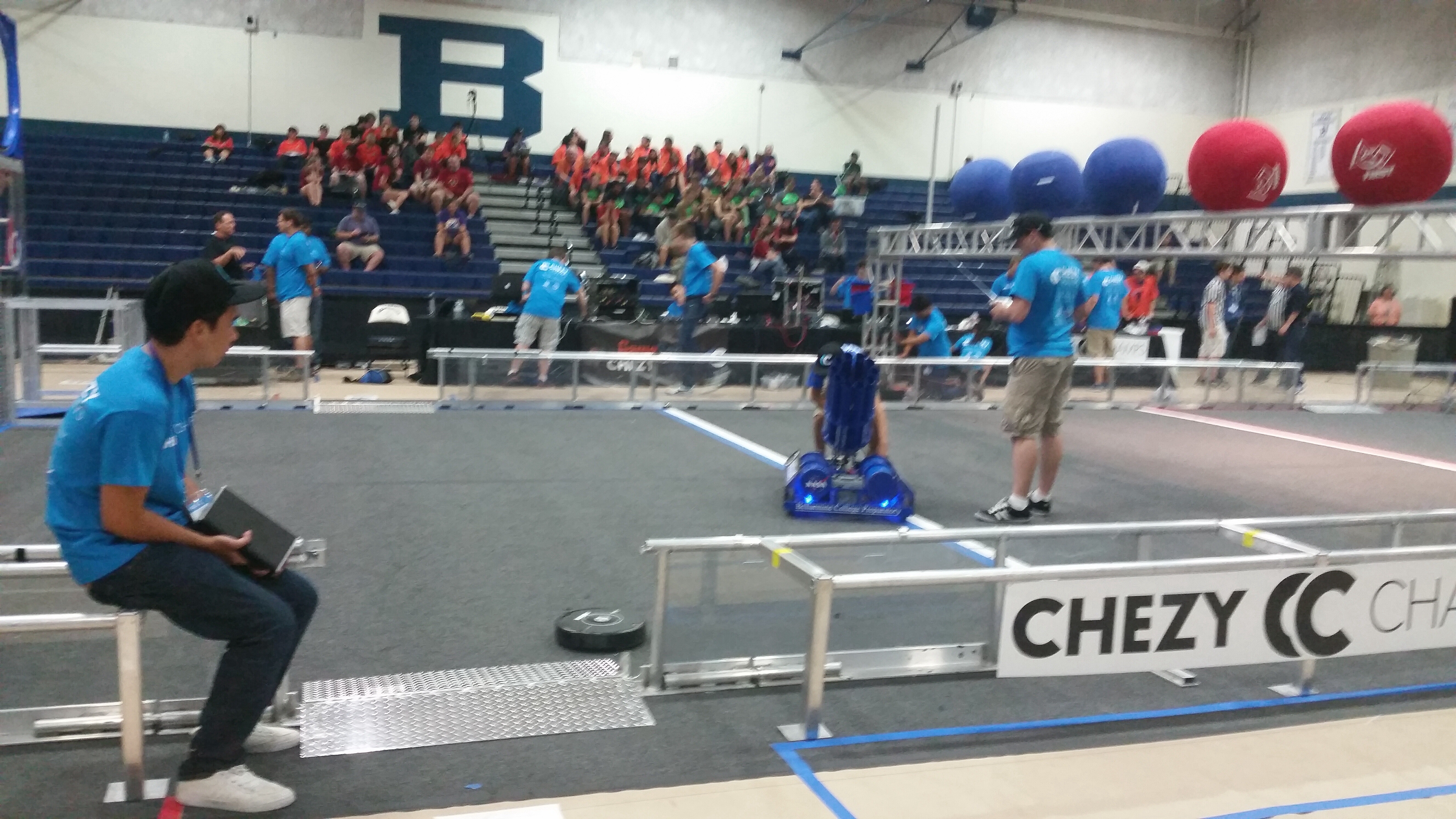
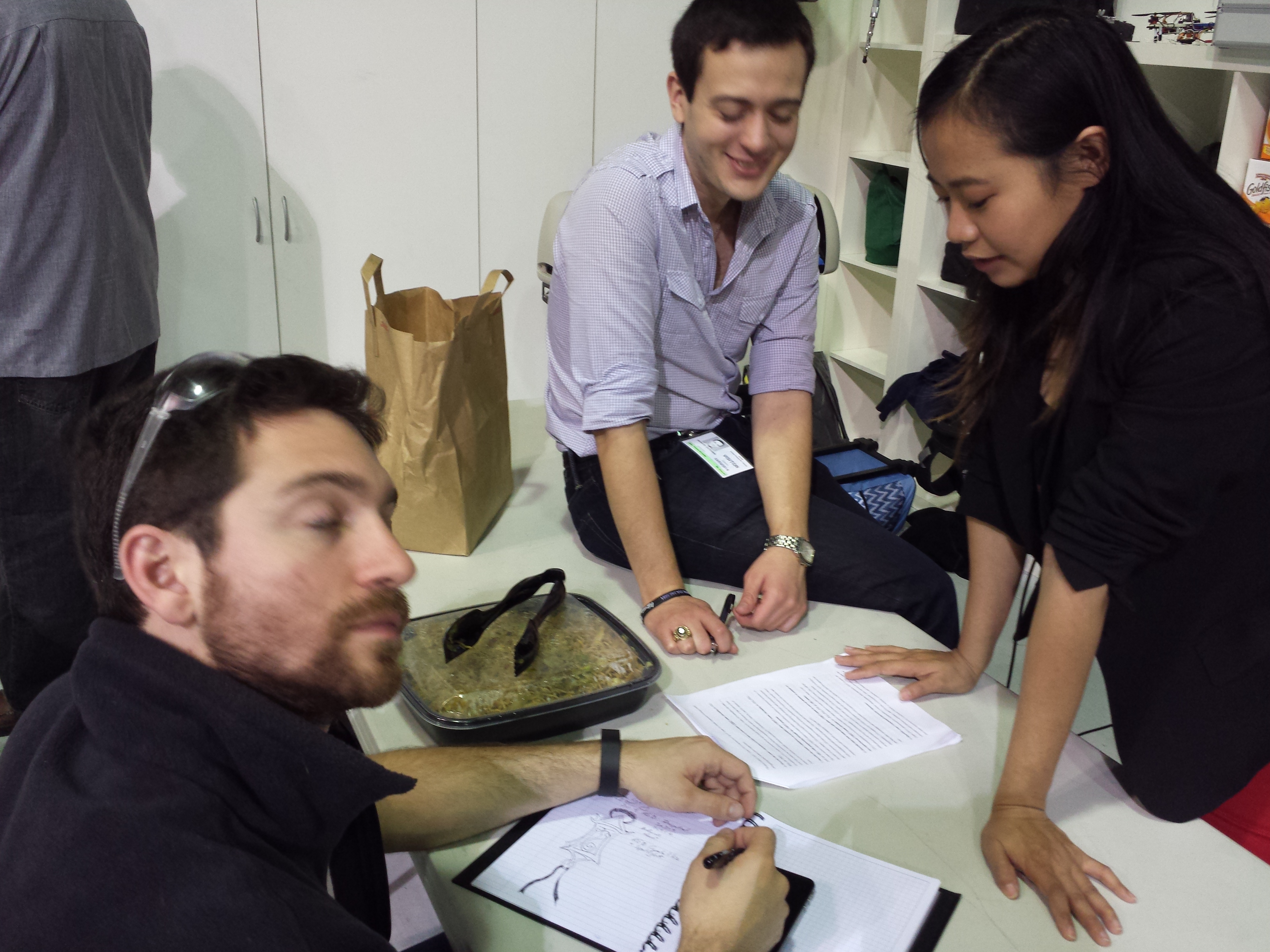
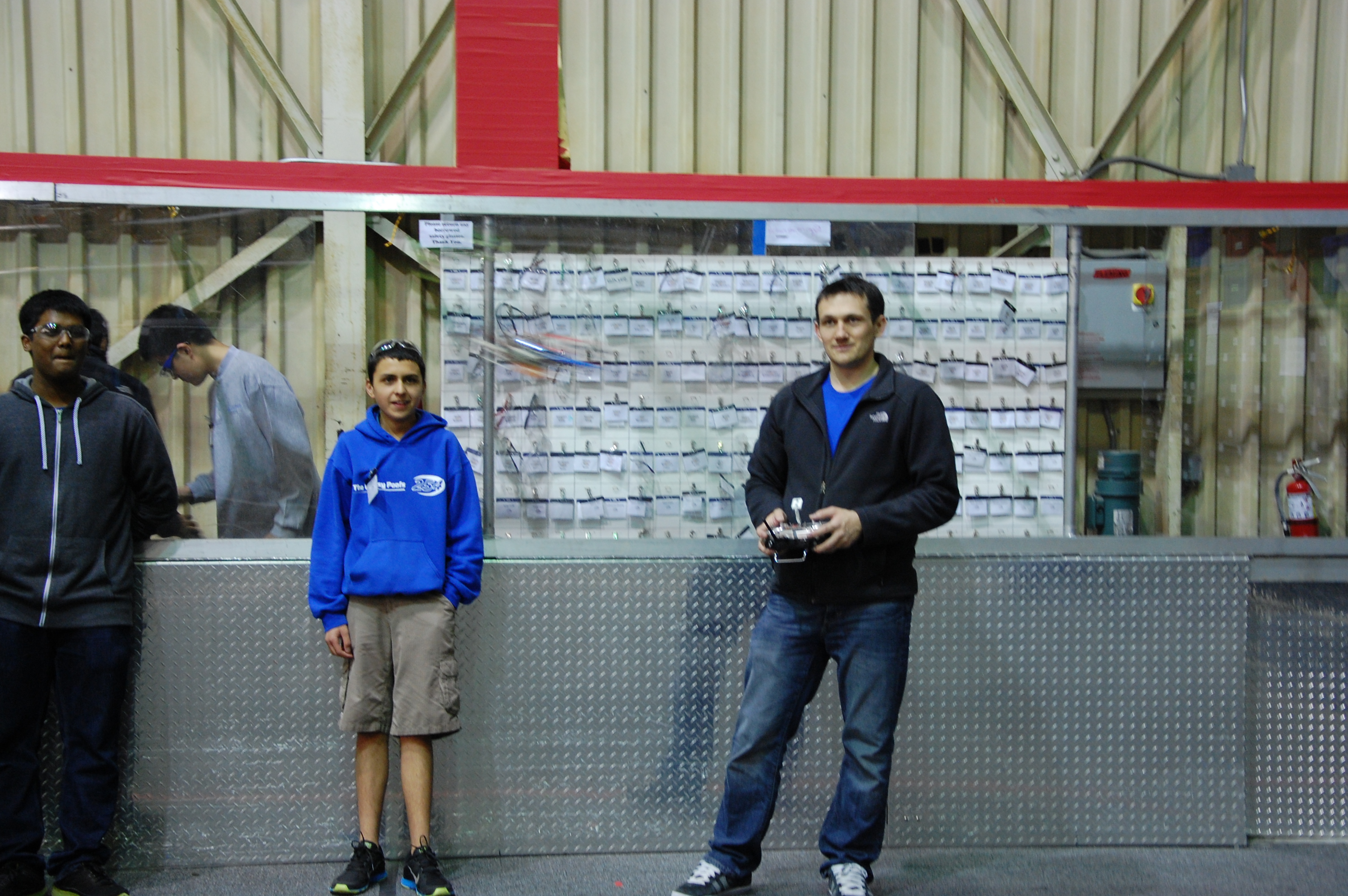
Chezy Champs: Behind the Scenes
Today teams from across the country gathered to compete in Team 254’s Chezy Champs Aerial Assist competition. After Friday’s hard work setting up the field and teams moving setting up their pits and robots, we’re ready to start a day of competition!
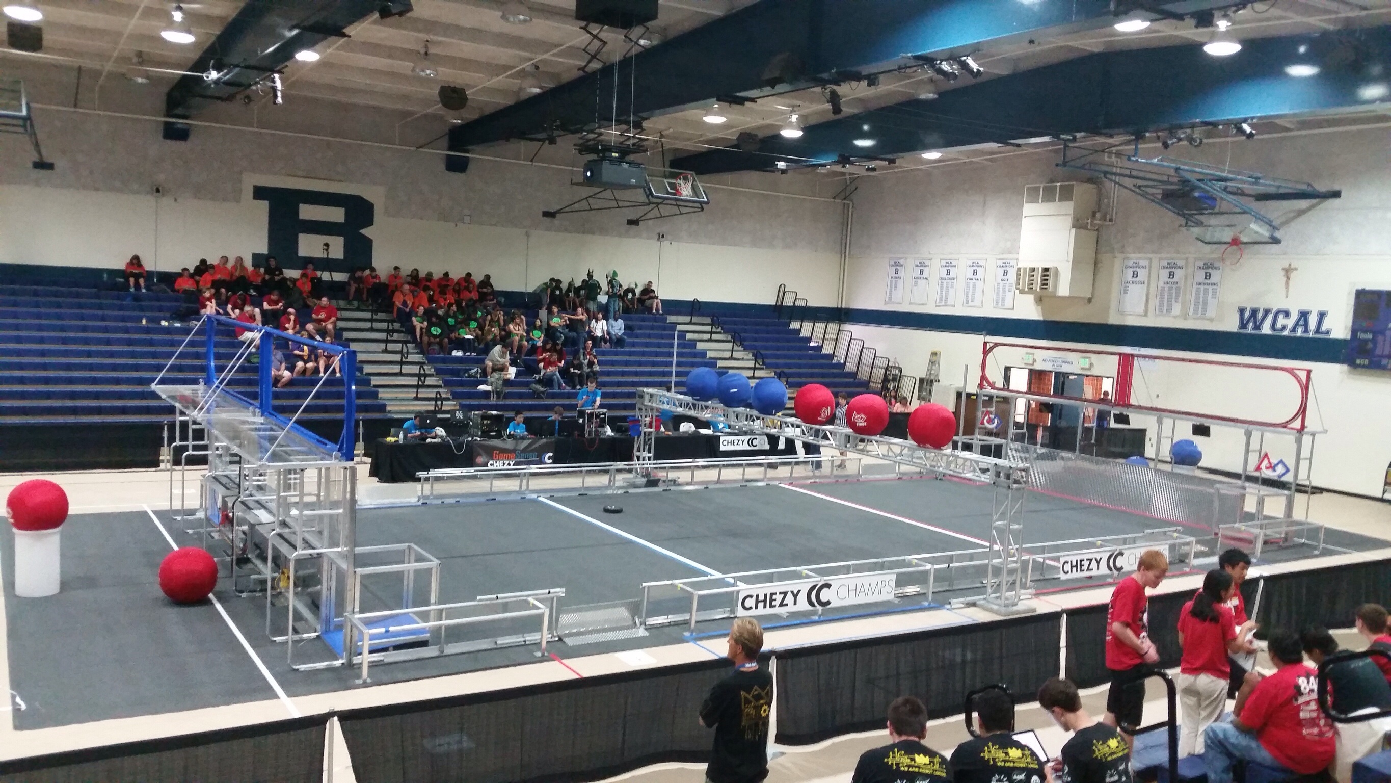
Pre competition hustle
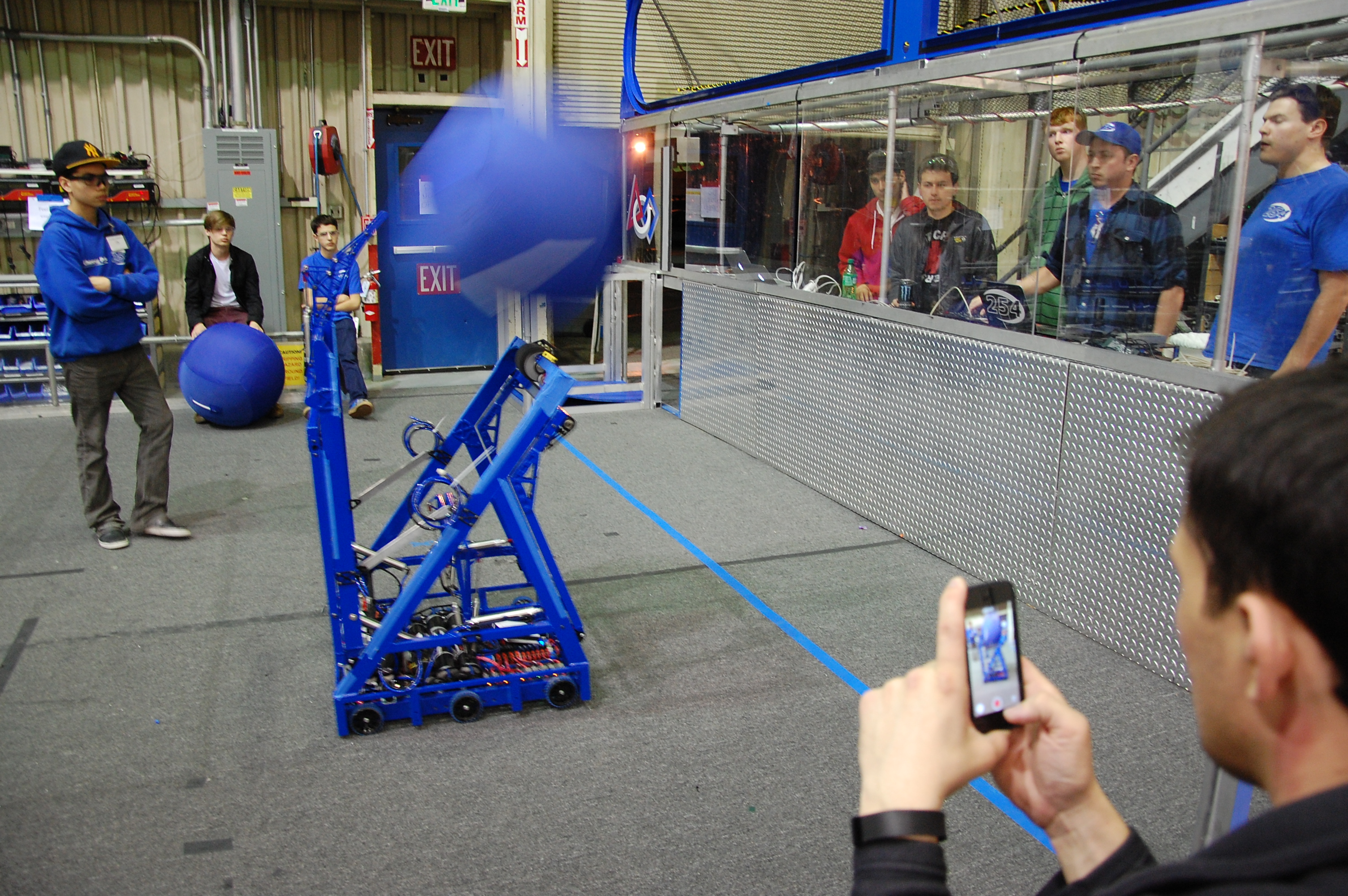
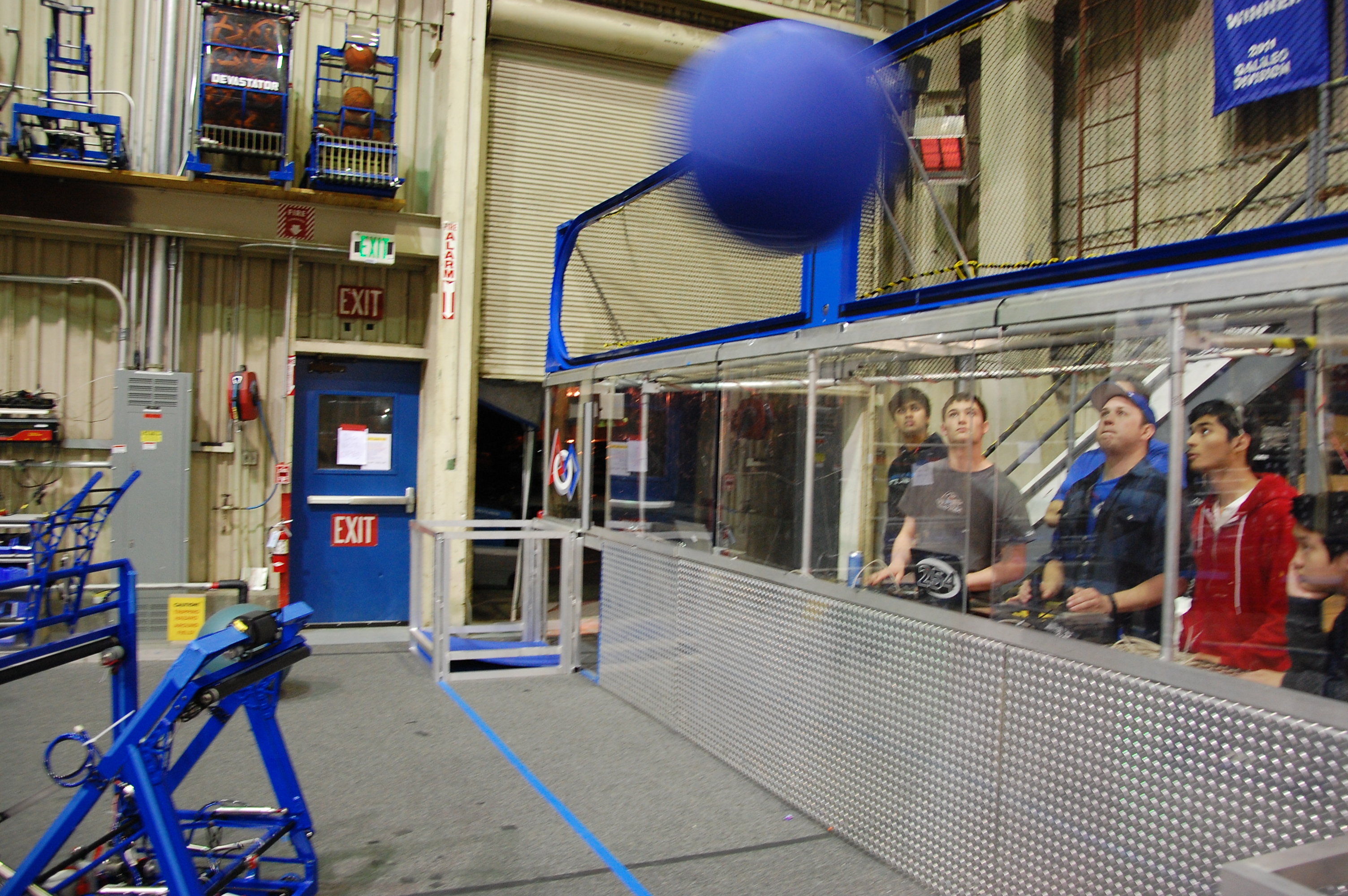
I love the smell of robots in the morning. Starting at 8am this morning, teams were allowed into the pits to start modifying and preparing their robots, and teams entered the Bellarmine gymnasium to stake out spots in the bleachers. And about half an hour later Shockwave was released and tested in the field.
Shockwave showing off for the crowd
At 9:30 the opening ceremonies began, introducing our emcee and game announcer, Karthik Kanagasabapathy and Paul Copioli.
Pre game pump up
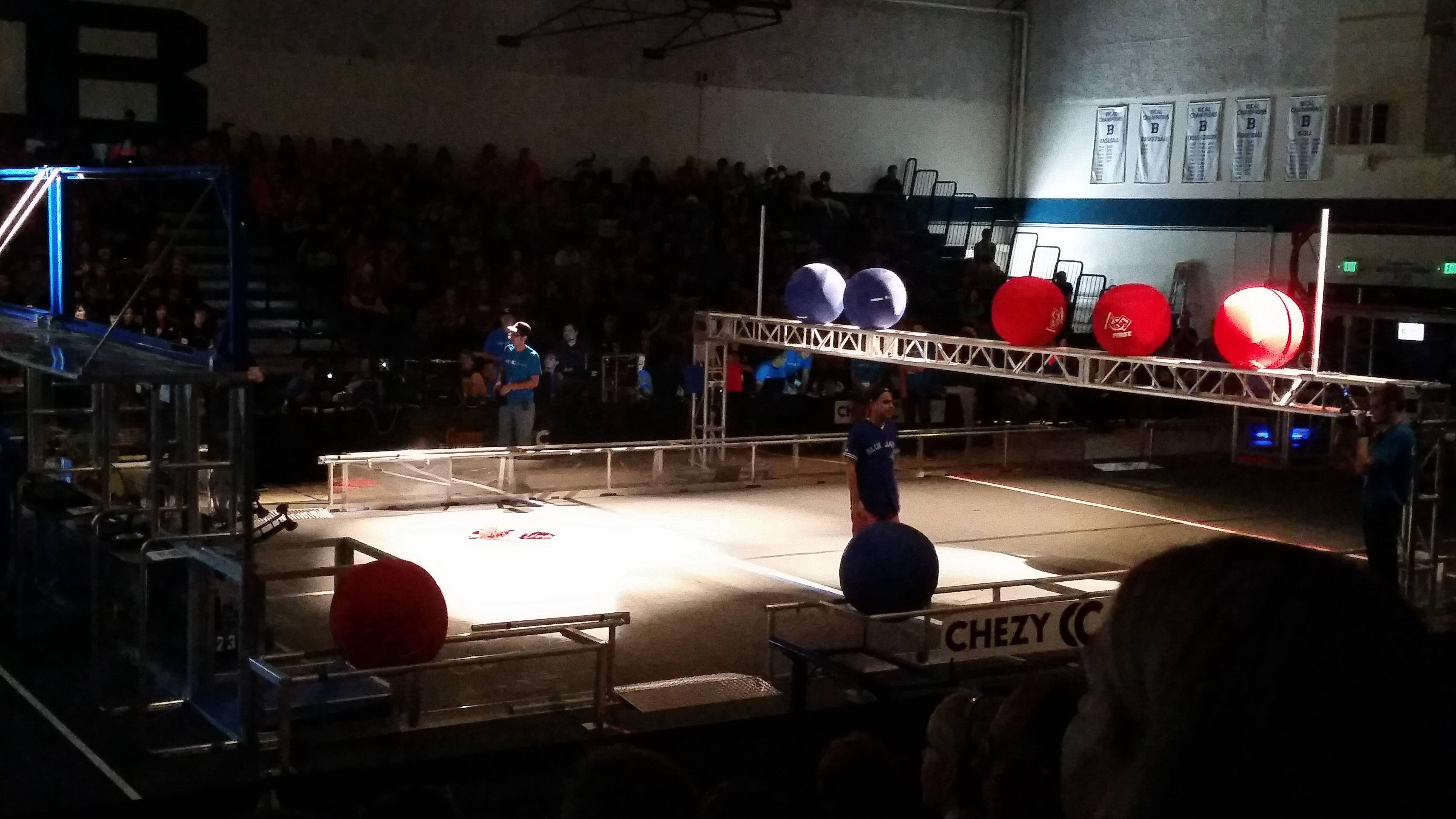
After all teams had staked out seats in the bleachers and the competing robots were in their ready position, at 10am the first match started!
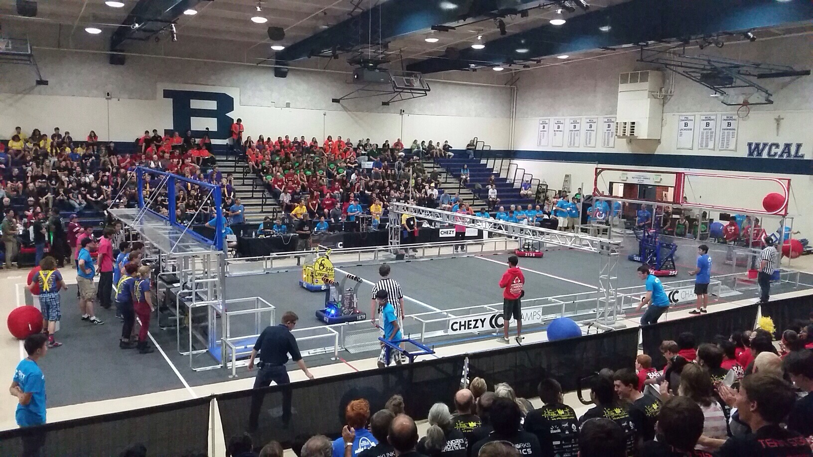
First match autonomous mode begins
After match 3 Shockwave decided to come out onto the field to compete with Karthick
SHOCKWAVE ON THE LOOSE!
After the first match I decided to take a walk around the facilities. Right behind the arena was the CC swag shop, where t-shirts, sunglasses and other swag were sold.
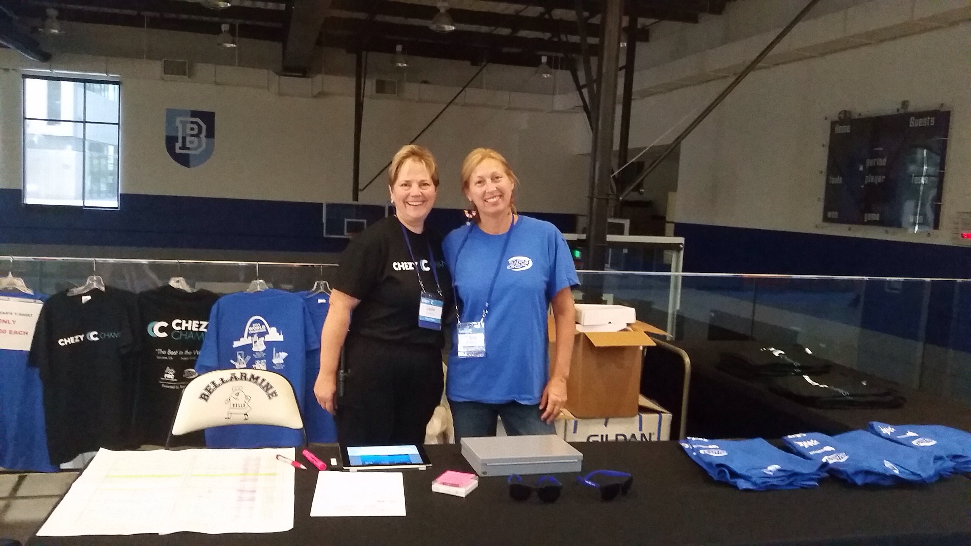
Two 254 moms manning the swag stand
I became aware that other items such as snap backs, volunteer shirts, and even life sized EJ faces (for the true EJ fans) were available through preorder.
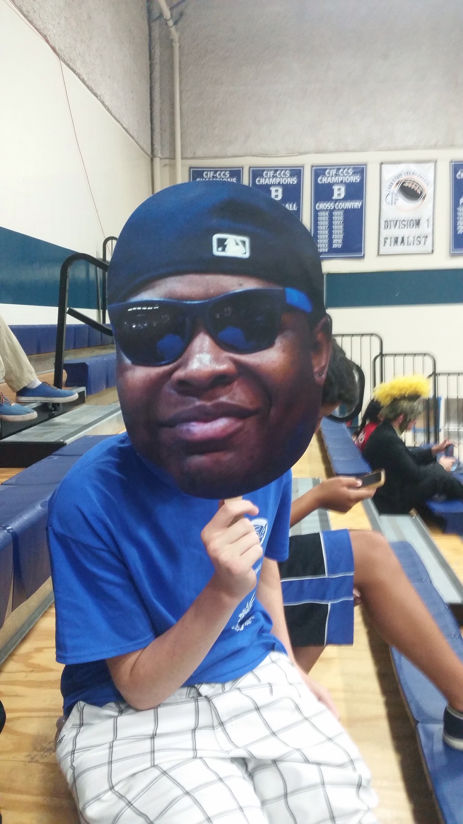
Team 254 member, Michael Ramstad, showing his pride with a life-sized EJ face
Next to the swag shop were the official Chezy Champs trophies, including the widely coveted golden corn dog for display of GP throughout the tournament.
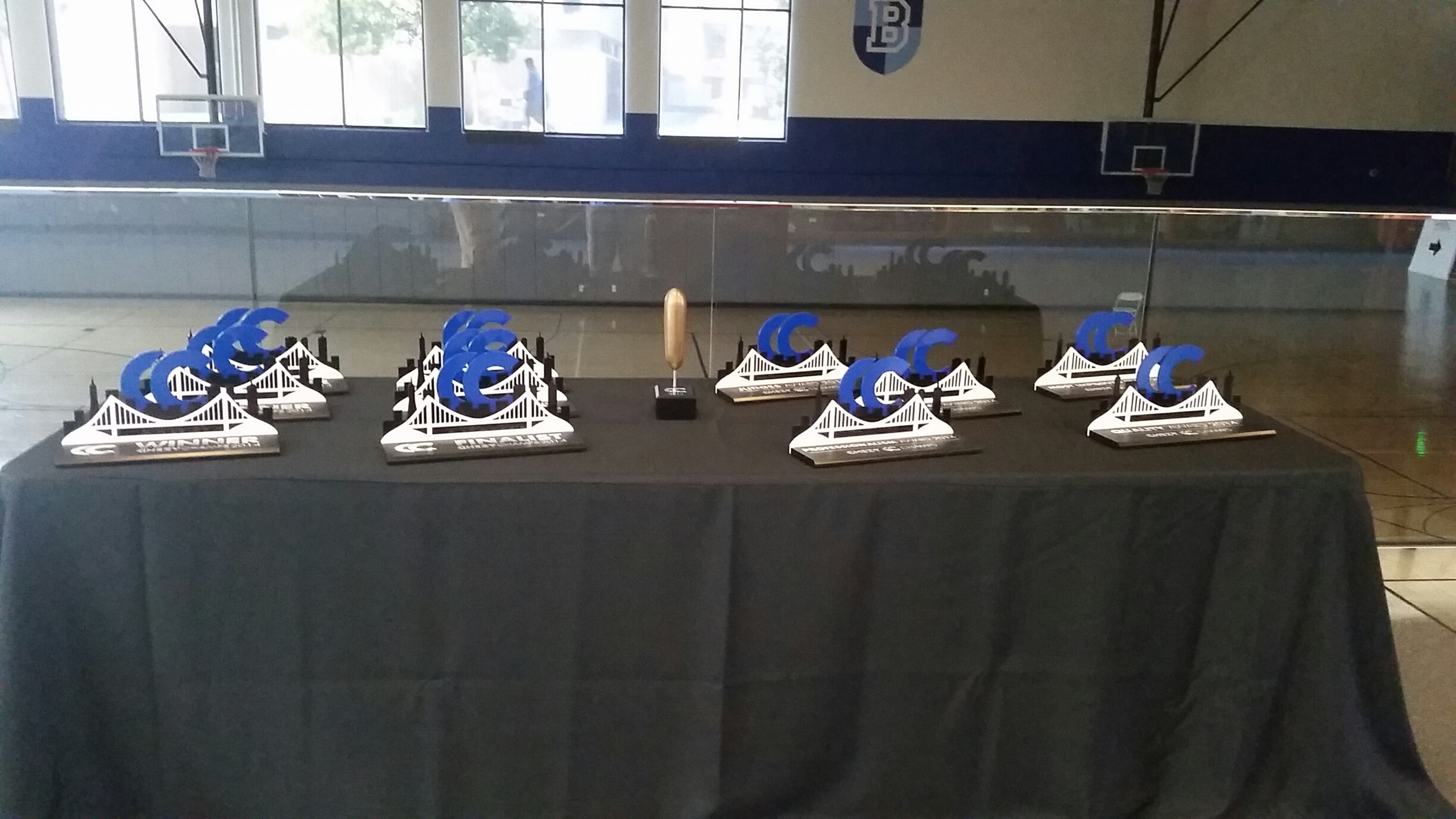
The glorious golden corn dog and other trophies
Lastly I headed out to the pit area in Liccardo to check out some of the other teams. At the admin desk, manned by 254’s glorious president Andrew Torrance, I checked in as a CC volunteer and put my super safety glasses on.
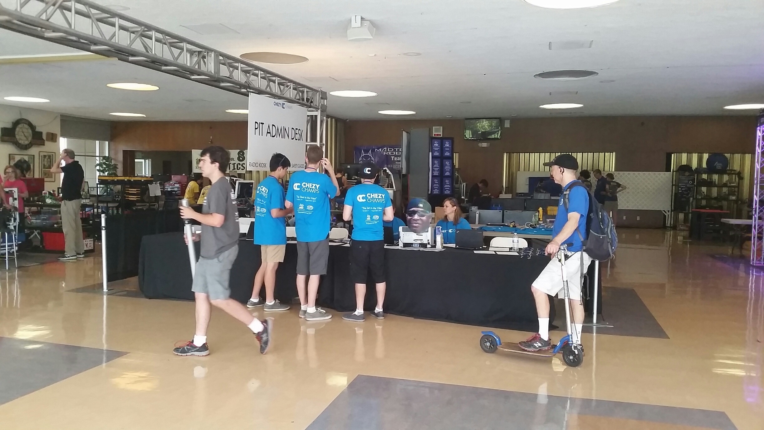
Staff surrounding our glorious student leader, Andrew Torrance
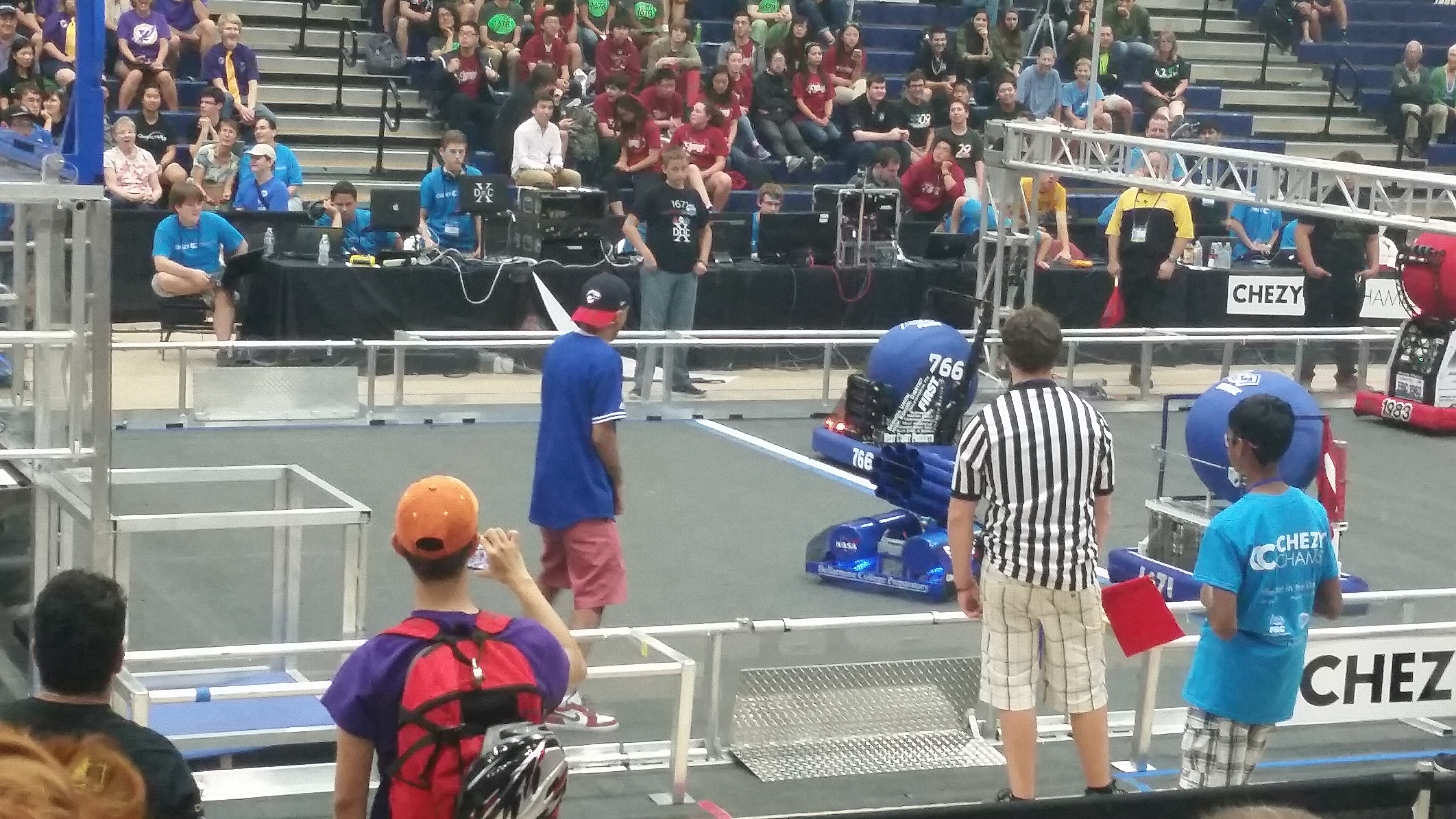
The first team I encountered in the pits was the Buchanan Bird Brains, Team 1671. A few members were willing to answer my questions about the tournament and their team:
Q: Where is your team based?
A: Our team is based in Clovis, California. It’s like the little brother of Fresno.
Q: What is the name of your robot?
A: The name of our robot is “Doc 10” because Doc Buchanan is the founder of our team’s high school and 10 because it’s team 1671’s tenth year competing.
Q: What does FRC mean to you?
A: FRC is like the family you never knew you had, and once you’re in the FRC family you never want to leave.
Q: What do you think of the Bellarmine campus?
A: The architecture is beautiful, it honestly looks like a college campus.
After interviewing the Bird Brains, I decided to talk to some of the teams at the other end of the pit. After a few minutes, I found that the Team 4201 pit was open for visitors!
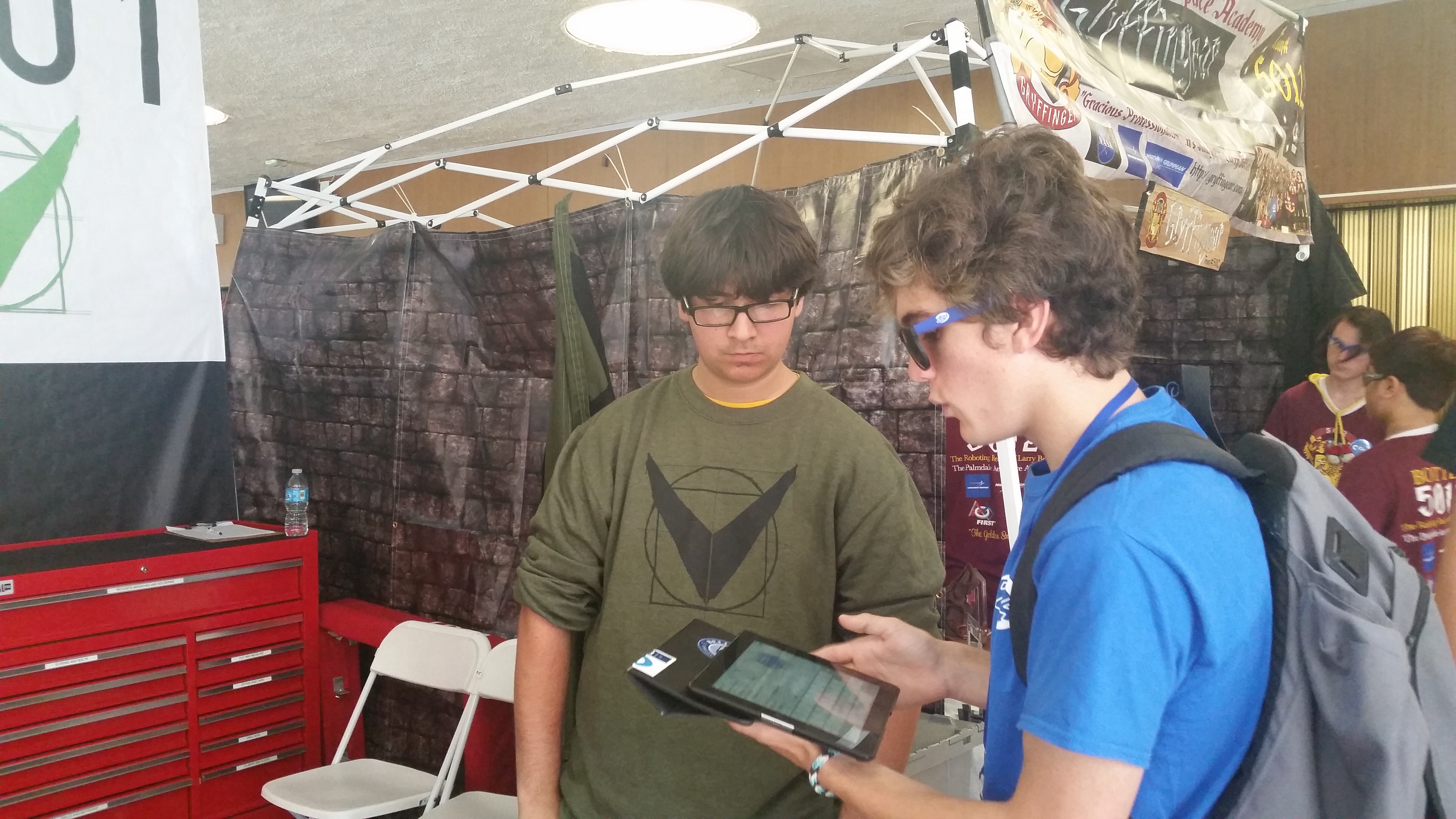
Me (in the blue shirt) taking notes on my interview with a member of team 4201
Q: Where is your team based?
A: Our team is based in Hawthorne, California near L.A.
Q: What is the name of your robot?
A: The name if our robot is #straightflexin. The # is part of the name, too! And it can’t be spelled out.
Q: What does FRC mean to you?
A: Since our school doesn’t really have any sports teams, this is our school sport. Like I used to play hockey but there was no hockey team. And, FRC is like the engineering version of a varsity sport. So for me it became a substitute for playing on a team in high school. Really it’s just the best thing ever.
Q: What do you think of the campus?
A: The campus is awesome, we really love your copper pipes. The water is so clean!
Next interview was with Team 696, the Circuit Breakers:
Q: Where is your team based?
A: Our team is based in La Crescenta in L.A. county, a little bit north of L.A.
Q: What is the name of your robot?
A: The name of our robot is Snapdragon. We actually have two robots, the one we use to compete is named Snapdragon and the practice bot we call “Snapdragon upside-down.”
Q: What does FRC mean to you?
A: FRC is one big family, once you’re in it helps you to stay connected with people who share your interests.
Q: What do you think of the Bellarmine campus?
Oh this is a high school? I seriously thought we were at a college. Wow, it’s really big.
After interviewing Team 399 I decided to visit the local food trucks for lunch. Outside we had the food trucks “sticks” and “scoops,” and inside food vendors sold everything from muffins to pizza.
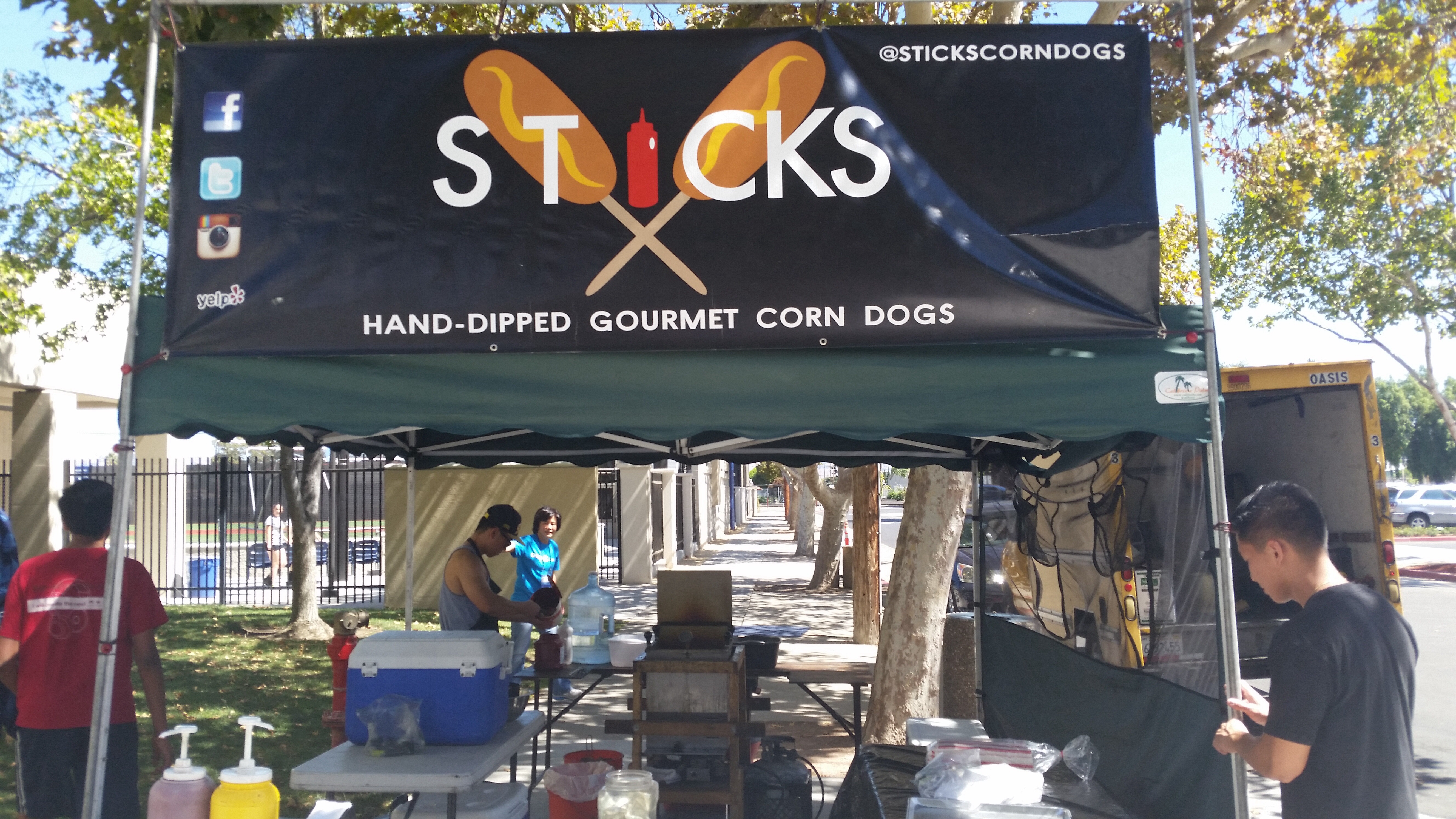
Jared must be so proud
After a short food break/nap in the field, I went back to the arena to make sure everything was ok. Everything was going very smoothly, and all the teams seemed to be enjoying themselves. None of our equipment was blowing up, there were no electrical fires, and none of the gaming servers crashed. I’d say that’s a success!
I had a lot of fun meeting and talking to all the different teams, and hope that the guest teams had just as much fun competing in and watching the matches as we did. Thank you to all the teams who showed up, and those who supported us by watching the event live on Twitch.
Go Poofs!
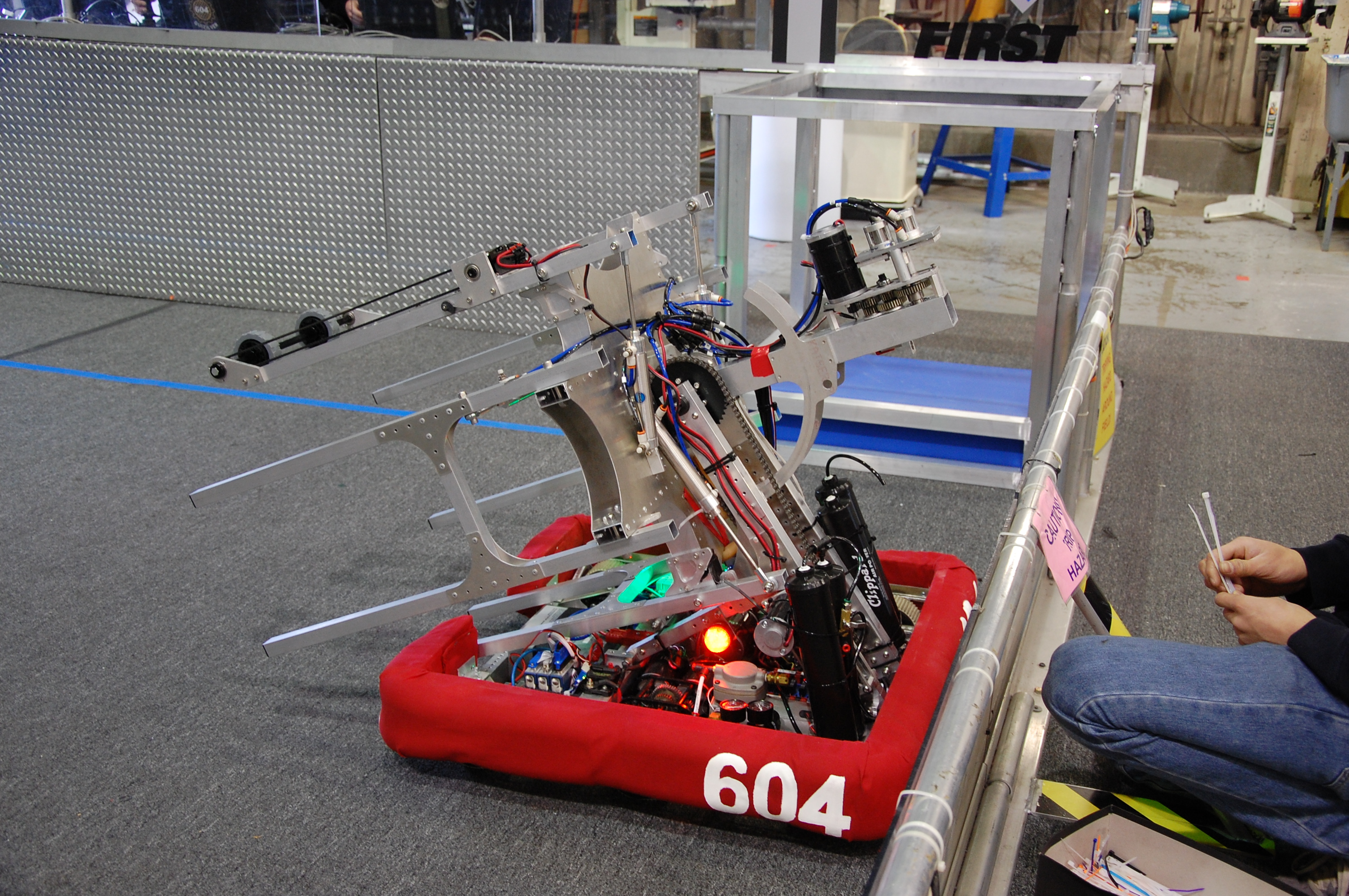
Day 43: Scrimmage Part 1
The Scrimmage
By Ryan Johnson, Louis Lin, and Alex Cherry
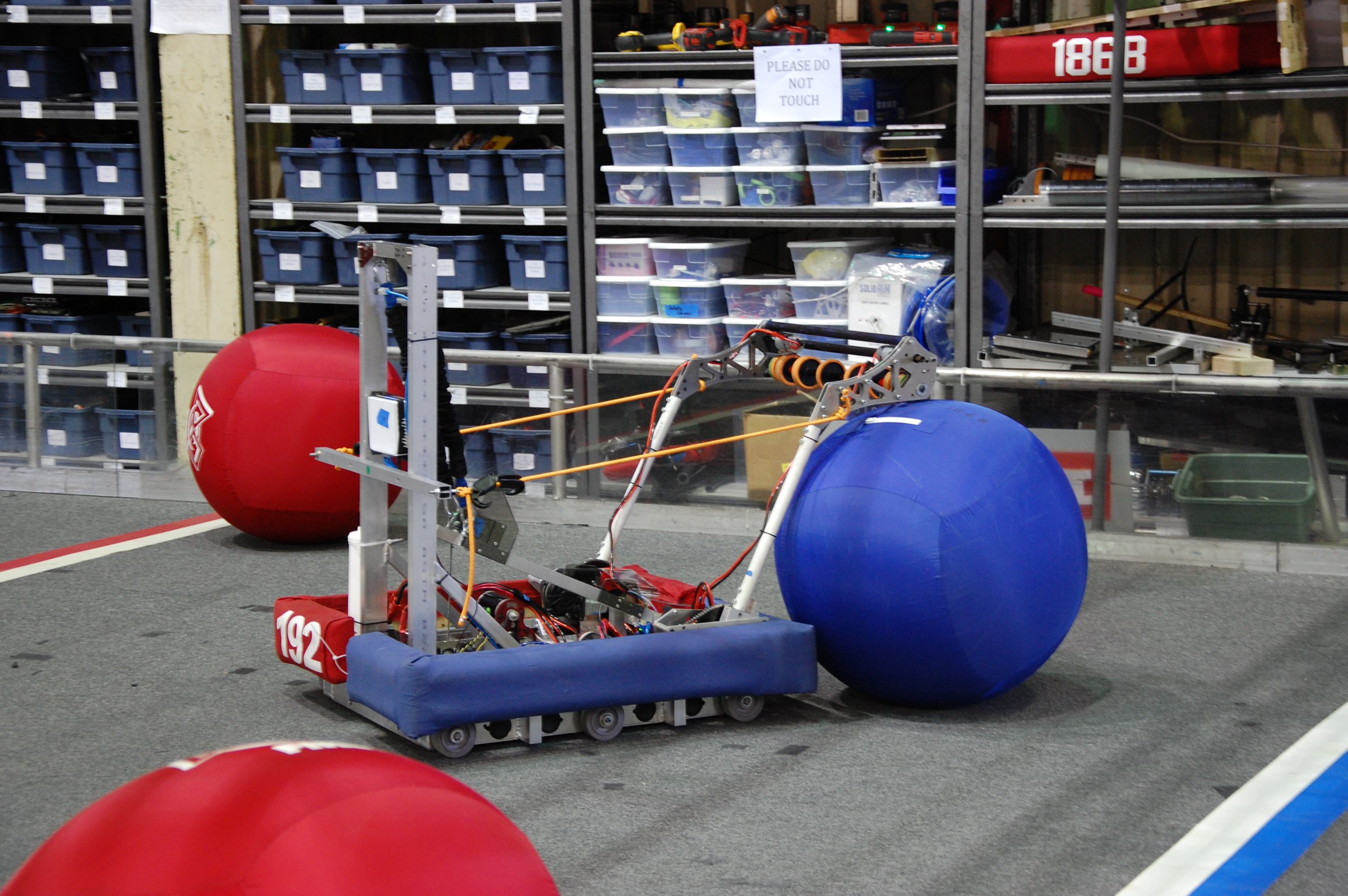
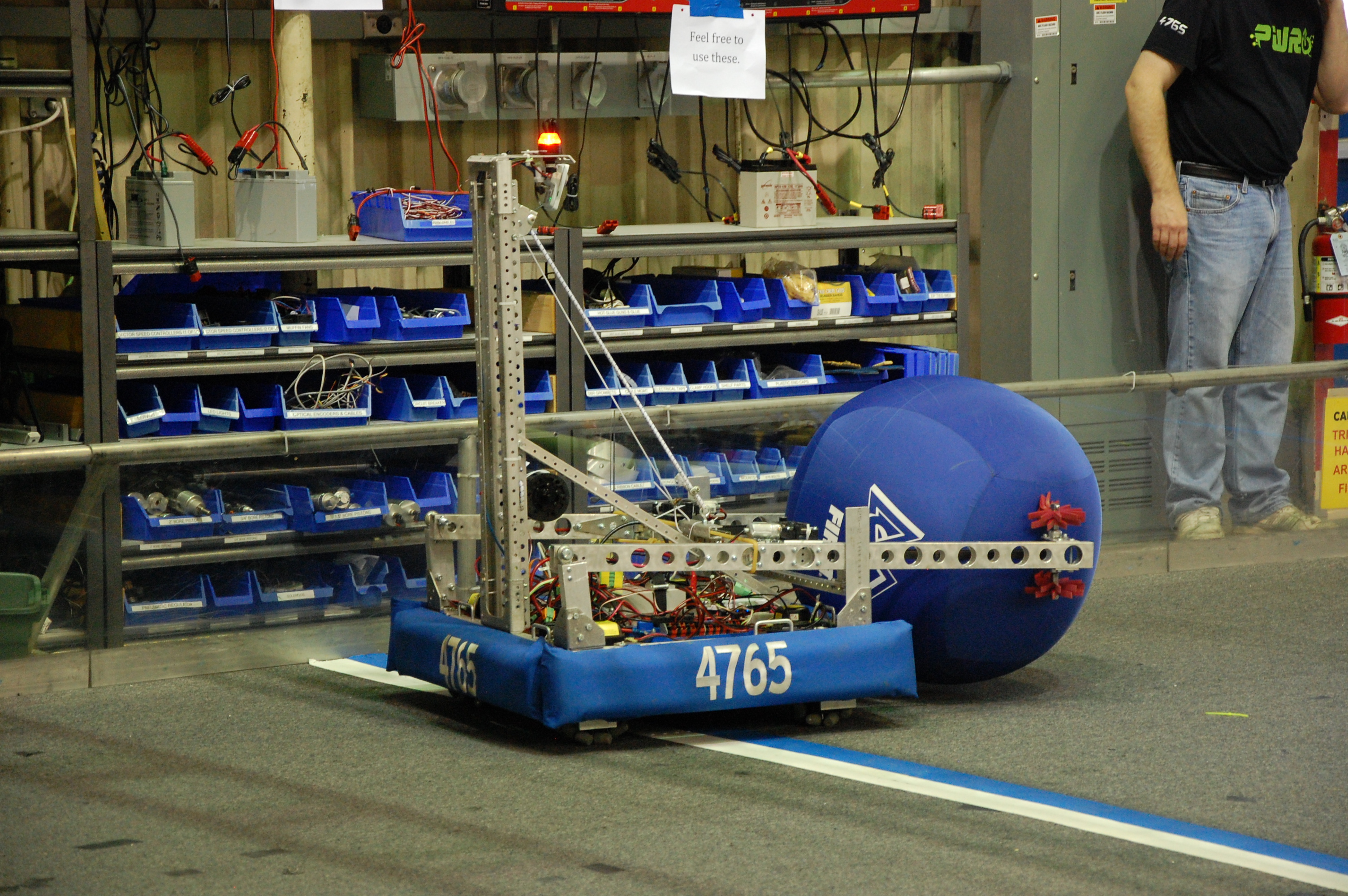
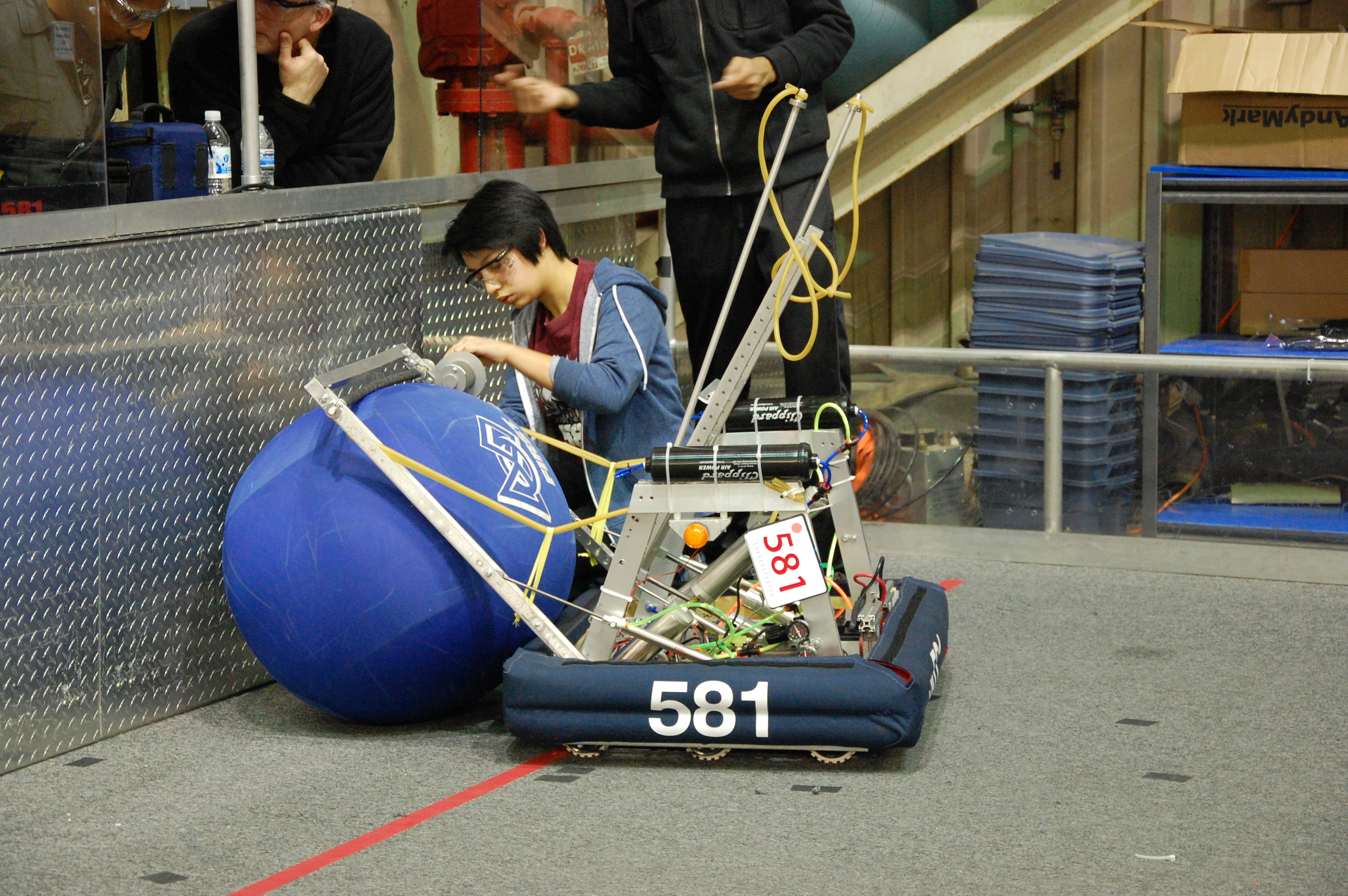
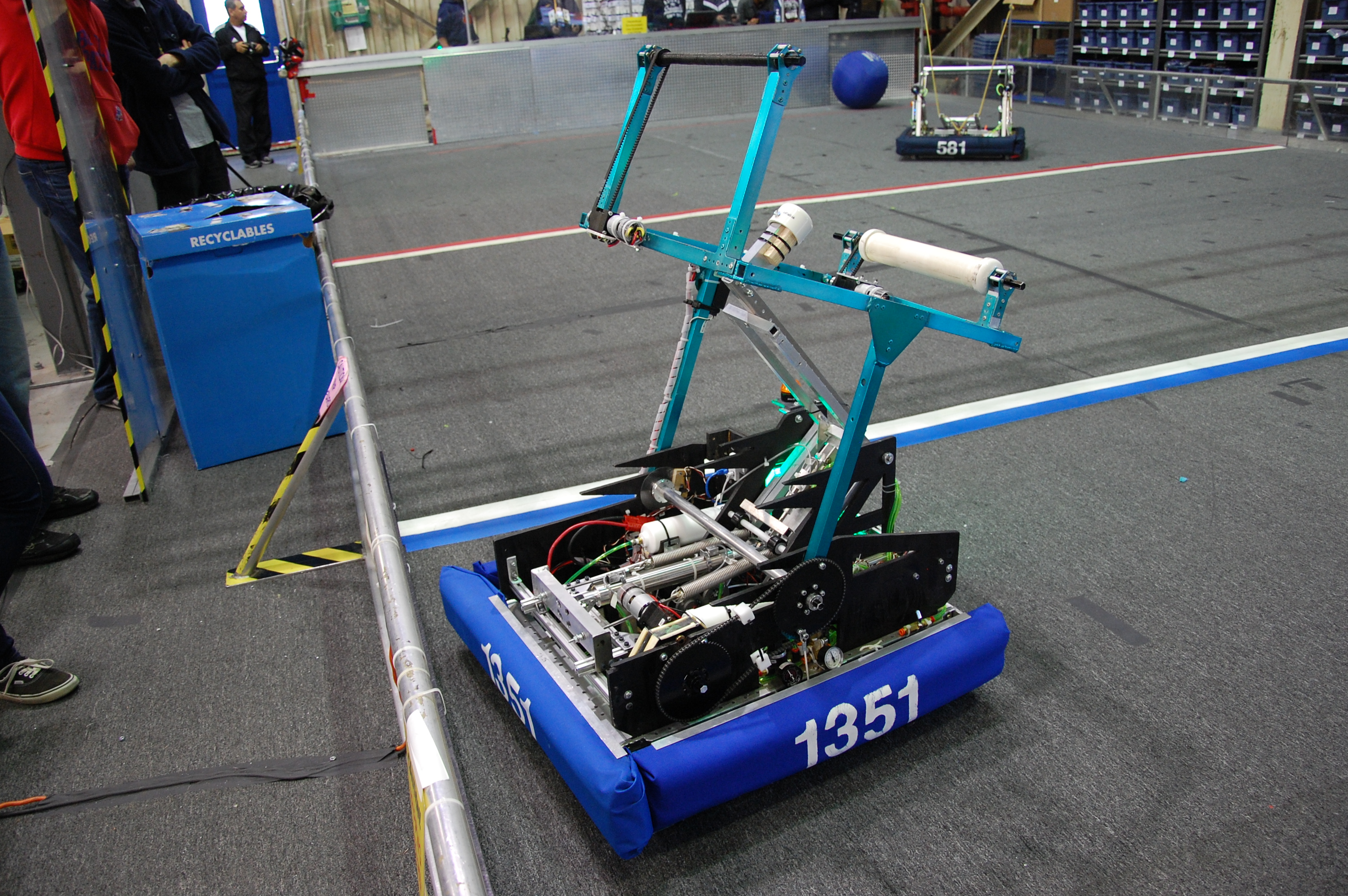
Team 604 (Quixilver), Team 192 (Gunn Robotics), Team 4765 (PWR up), Team 581 (Blazing Bulldogs), Team 1351 (TKO), Team 3501 (Firebird Robotics), Team 4990 (Gryphons), and Team 2813 (Gear Heads) all shared our lab today to practice on our almost full size field. Since most of the teams don’t have access to a field often (if at all), it allowed them to tune their robots so that they score, pass, catch, and move better.
Wiring and Assembly
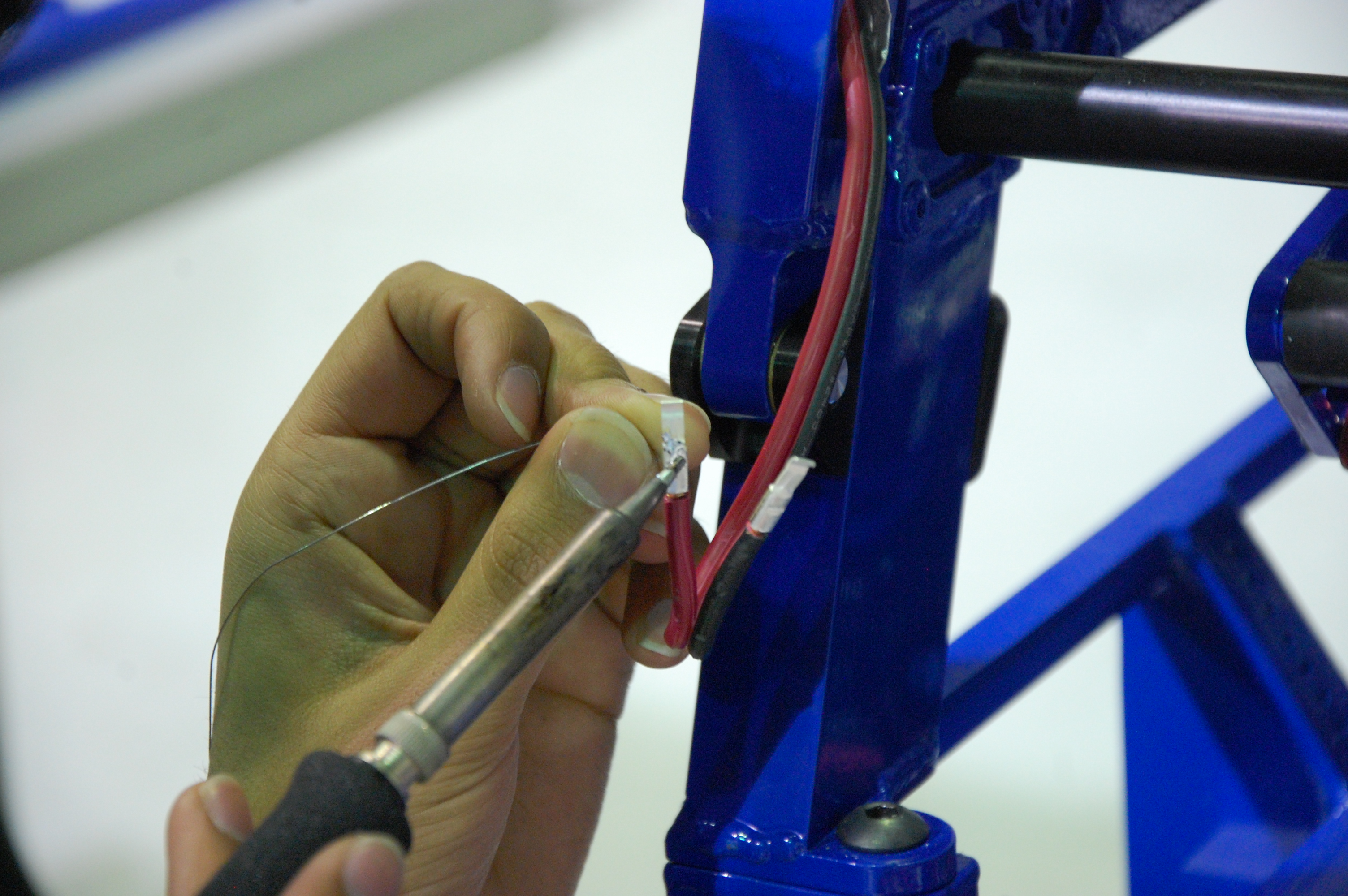
While the other teams were testing their robots, we were finishing the wiring on our practice and competition robots. Specifically, we were working on wiring bump sensors and Intakes. We also worked on finishing the hood. Aside from a couple of parts and wires, the robot is mostly built.
Manufacturing
A Couple of our team members worked on manufacturing piston parts, and a couple of members worked on assembling the bumpers. The pistons that they are working on create a unique linkage between two pistons where one piston “locks” the other piston in place so that the rear intake can be locked up when shooting.
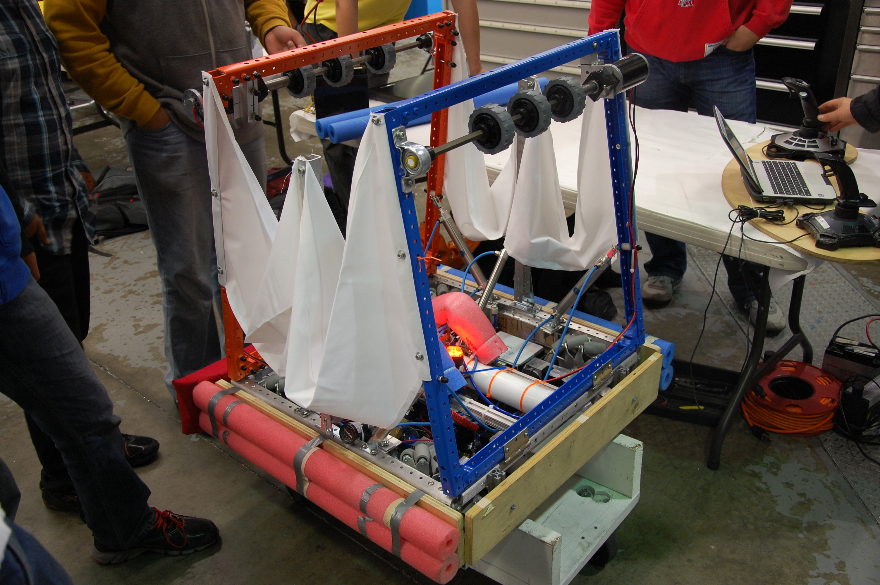
The bumper team started making two blue bumpers. Students affixed pool noodles along each side of the wood bumper frame with gaffers tape. Then, they stretched a full loop of cordura fabric around each bumper and stapled it down along the inside. Students took extra care to eliminate as many wrinkles as possible on the bumper fabric.
Shot Testing
As students tested the robot shooter, they noticed that the ball was being impeded by something before it touched the shooter flywheel. Using a slow\-motion camera, they were able to observe the process of the clappers pushing the ball up the shooter. Programmers adjusted the timing of the clappers to push the ball up vertically. Then, they adjusted the power of the clapper pistons to optimize each shot.
Action Items
\- Finish Assembling Bumpers
– Finish Assembling the robot
– Make Robot Flyers
– Make the Robot Binder
– Program the robot
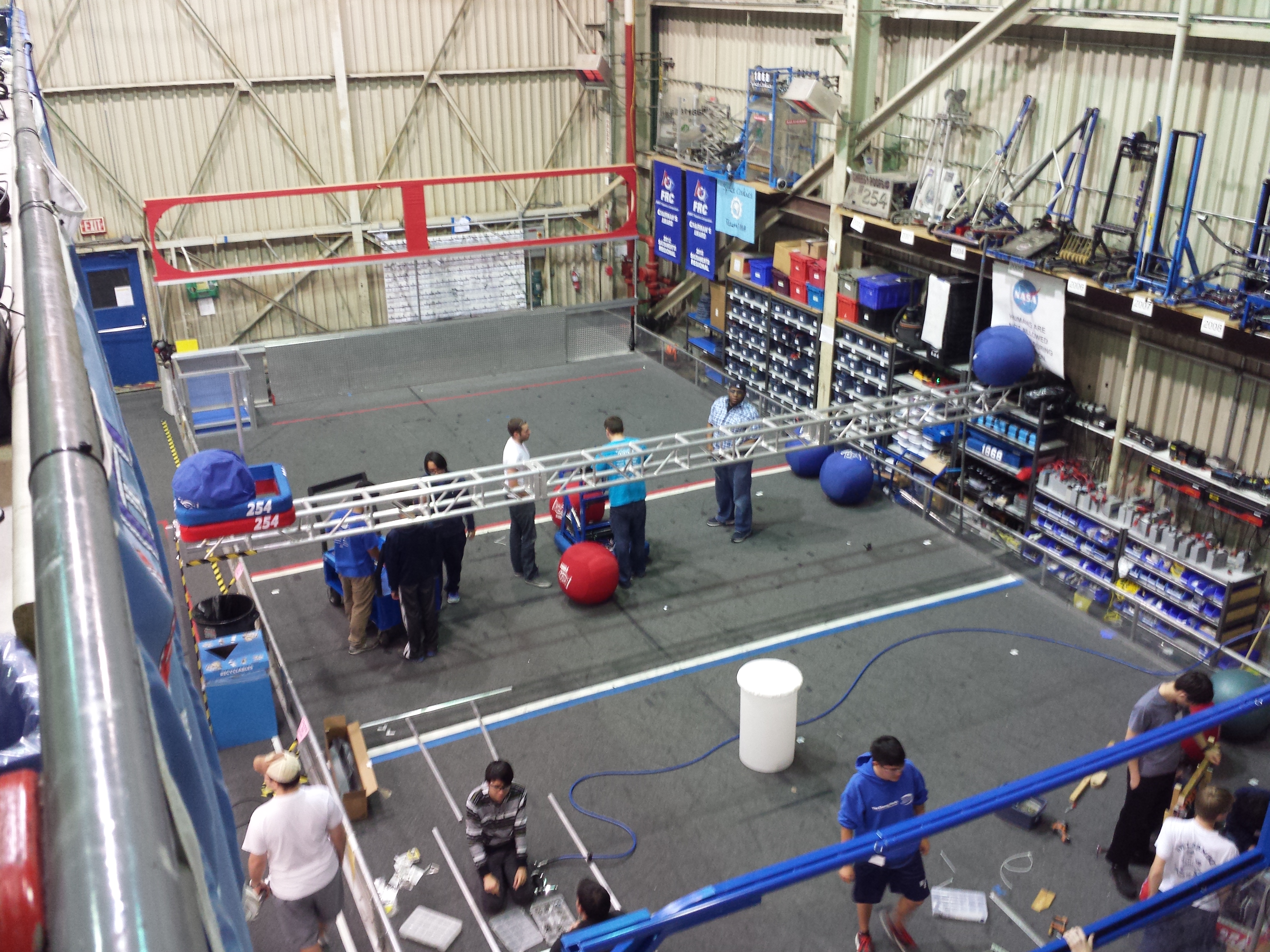
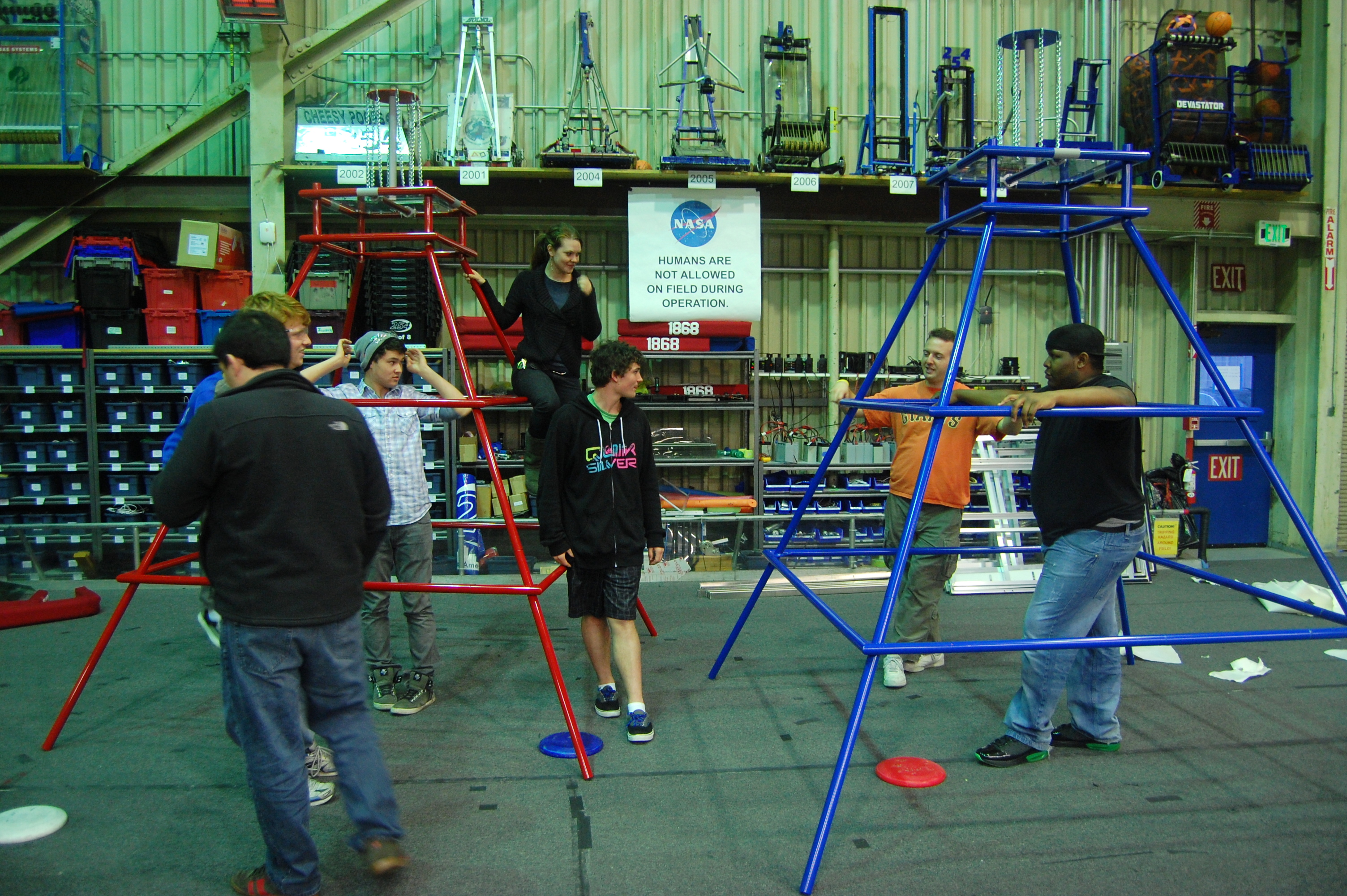
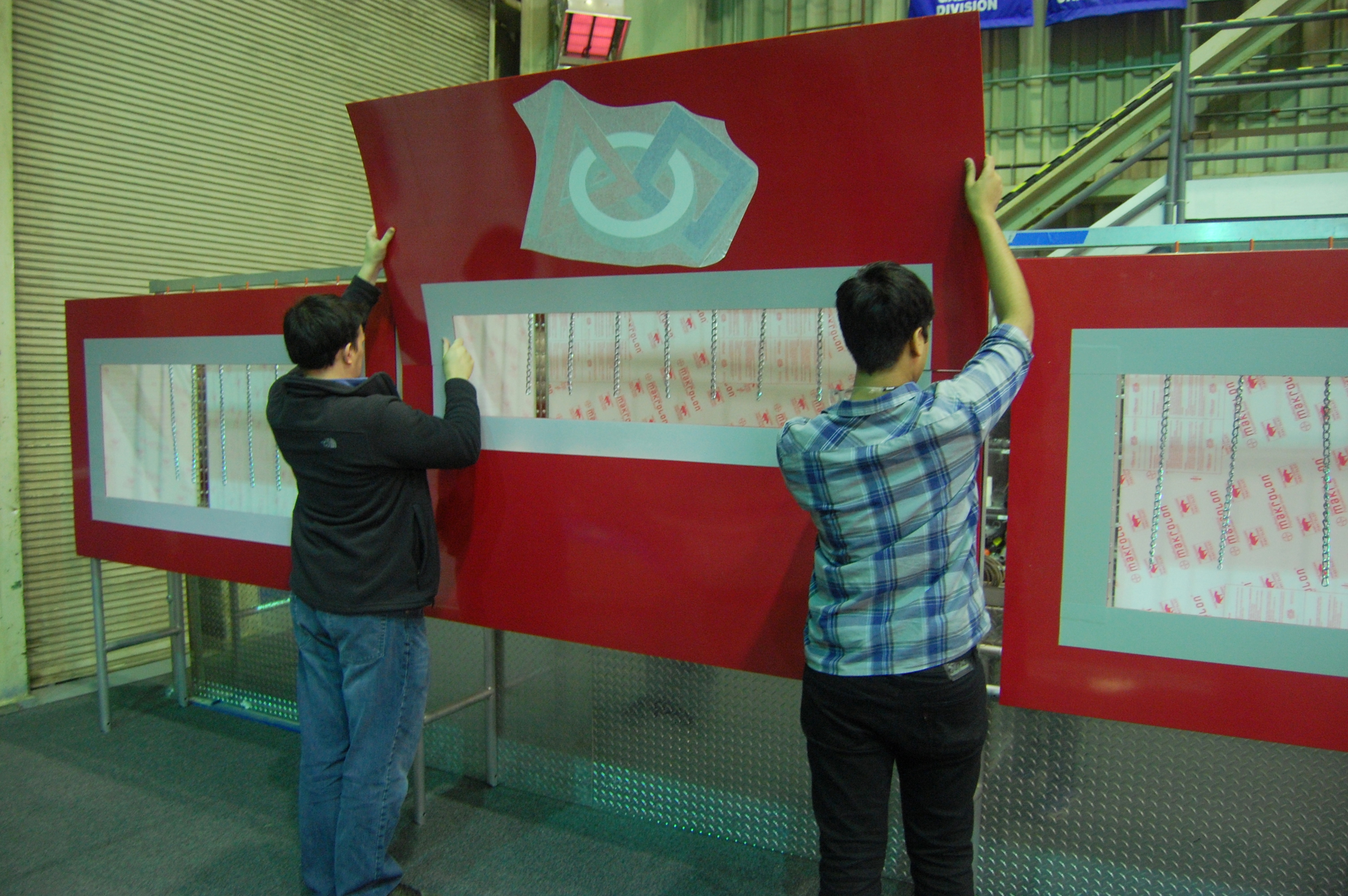
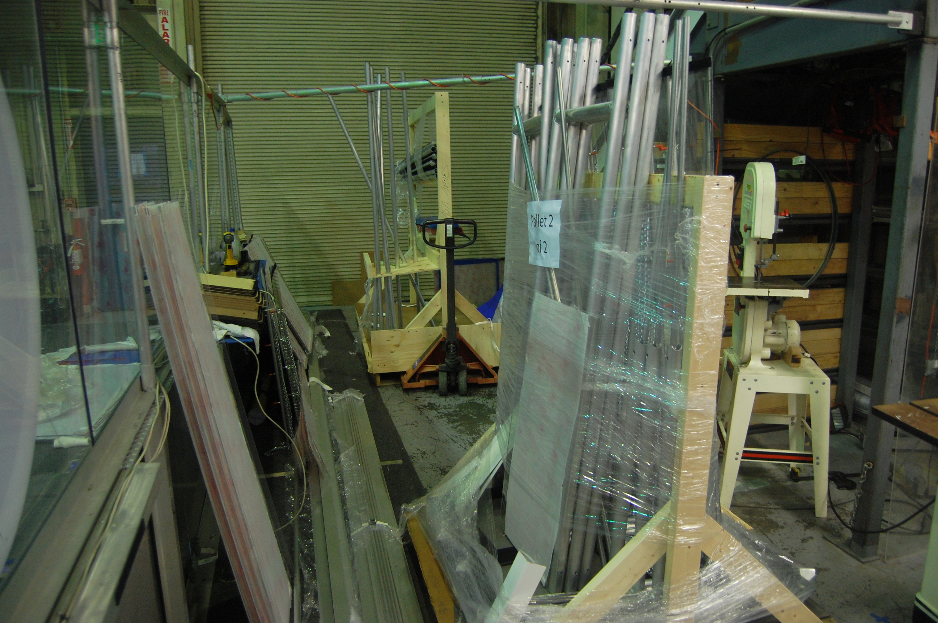
Day #31: Field Assembly
Practice Field Assembly
Without a doubt, the highlight of the day was the arrival of the official field pieces. Students spent much of the night organizing the many parts that arrived at the lab today and assembling the field elements themselves. The pyramids were the first objects completed, with both pyramids being fully assembled by around 6 pm. Between completion of the pyramids and dinnertime, students worked together to unpack and sort various field components, as well as cleaning up miscellaneous parts lying around in the lab to make way for the new arrivals. After dinner, the whole team got right back to work putting together the goals, the trusses they rest on, and the corner feeder stations and low goals. Due to size constraints, we will have only 2 of the 4 corner feeder stations, and the goals will need to be mounted in a unique way. The netting will be assembled at a later date. The field is very large, but also really unique and cool. We are excited to have the official setup and will begin practicing as soon our robot’s shooter and climber are functional.
Programming
Though the field assembly was the main job of the night, other tasks were being worked on as well. The programming team began the night by working on fixing the Cheesy Drive code to address the issues that had been discovered the night before. The deadband value of 0.1 was found to be too high, so it was reduced to 0.02, a value judged to be more reasonable given deadband values from prior years. An investigation is currently ongoing into what is causing a strange drive bug where rapidly switching from full forward throttle to full backward throttle causes the robot to exhibit unusual “jumpiness” while on low battery. Finally, work continued on finishing a graphing system for the Smart Dashboard.
CAD
Students and mentors continued work on finalizing the CAD. Currently the intake has been finalized, and the conveyer and shooter are close to being complete. The climbing mechanism position has been determined, but mounting is still being finalized.
Machining
Students used the mill to make aluminum angles to mount the wooden bumper segments together. Once the wood segments are complete we can assemble the bumpers.
Students also used the lathe to make shafts with snap ring grooves for the conveyer. These will be used with the Polyurethane Tubes and mounted once we finish machining the rest of the superstructure.
Action Items
- Complete field assembly
- Contnue investigation on Cheesy Drive
- Finish grapher for Smart Dashboard
- Continue machining parts for the superstructure
- Finalize the CAD of the converyer, shooter, and climber
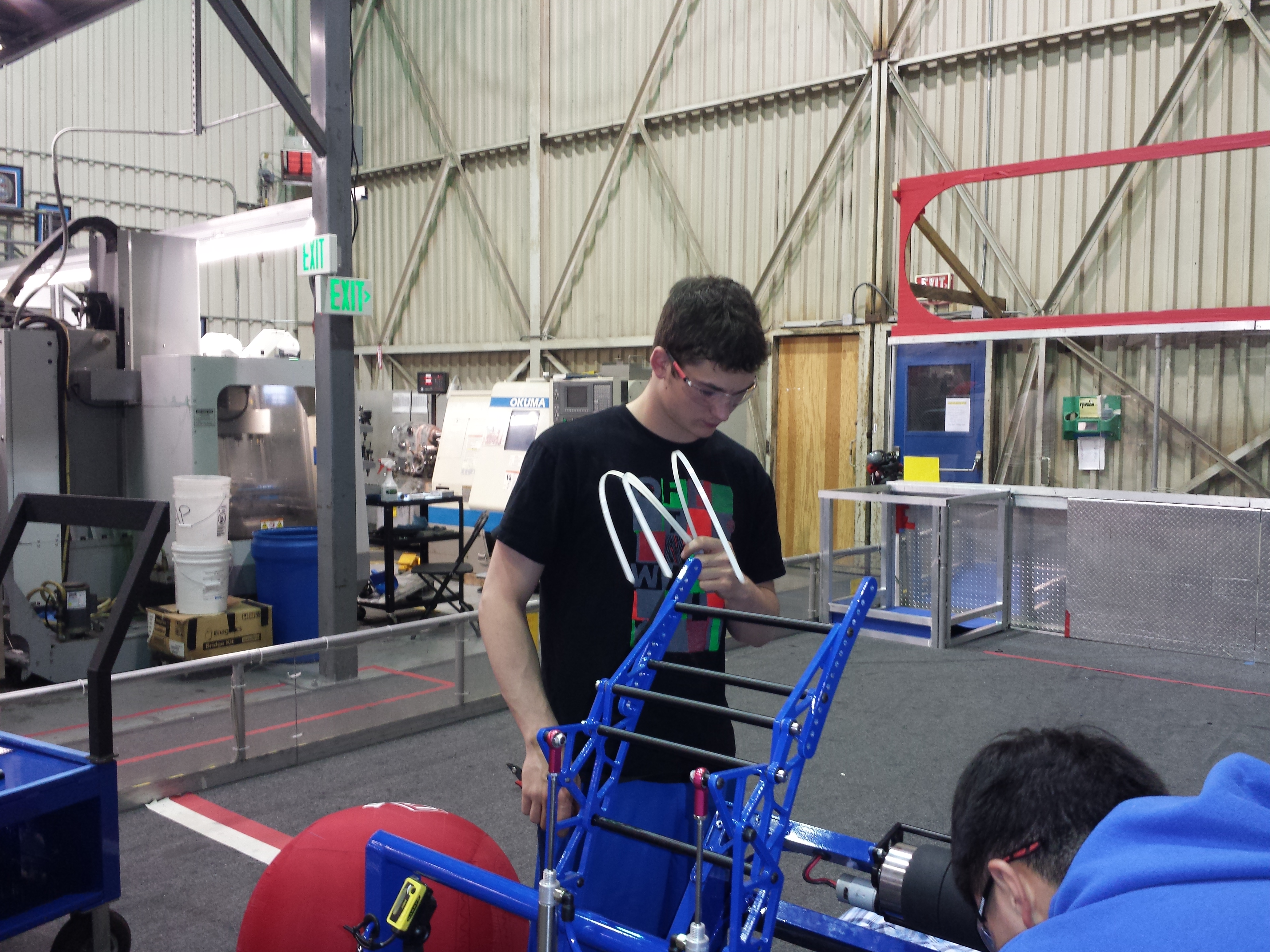
Day #9: New Intake
Prototyping
Shooter
Students have made a couple of modifications to the shooter prototype. An L channel was added, in addition to guide rails. A pneumatic piston was attached to the shooter to load the frisbees into the shooter wheels.
The goal was to make a shooter that could shoot frisbees both upside down and right side up. After making the modifications and adding the "autoloader" the shots became more consistent (because of the same loading dynamics). However, the upside down shots and the right side up shots were aiming differently. The most significant difference is the flying dynamics. The upside down frisbees were more unpredictable and didn't fly as well.
Students making enhancements to the shooter
Conveyor
Not much was changed on the conveyor. Upon the completion of the shooter and intake, students will integrate the conveyor design with the two other prototypes.
Conveyor prototype
New Intake
The team took a new route with the design of the intake. They removed some of the orange polyurathane belts in the process. A new intake was constructed from the CAD. Though it works fairly well, the team is working on improving it. It can't quite take two frisbees at the same, but can still pick them up quickly. The design is based on the old conveyor prototype and old intake prototype.
At the end of the night, the intake was fully functional and was able to funnel two frisbees into one. It was also able to easily pick up the frisbee from the ground, albeit not as well as was hoped. The intake so far is not fast enough and not consistent enough. More work will be done on it tomorrow.
Building the new intake
Programming
The programmers worked on a Smart Dashboard widget for writing constants and their values to a text file, and uploading them to the robot using FTP. They first worked on the layout of the widget, and were successful in the writing and clearing functionalities. However, the programmers still had issues creating an FTPClient object and connecting to the robot.
Dorian Chan programming the Smart Dashboard widget
Students also wrote a Turn Command for use during autonomous mode. The ScriptedAutoReader was configured to read the word "TURN" as a TurnCommand and appropriately create one. It seems to work, but the command still requires extensive testing, since the command depends on the gyroscope and the robot was left on the stand.
Richard demonstrating turning in real life
Miscellaneous
The pyramid was fixed. The top goal of the pyramid was brought down for some adjustments, and then reattached.
Fixing the pyramid goal
Action Items
-
Continue work on intake (make it work)
-
Make shooter accurate
-
Do math, save world
Lab closing time for the night was 2:00 AM
CalGames 2012

This past weekend Team 254 attended CalGames 2012 at Woodside High School, an off-season replay of the FRC game Rebound Rumble.
After 4 wins and 4 losses in qualification matches, 254 was the first alliance choice for the #1 seed, Team 971. Later joined by Team 766, the #1 alliance proceeded through the elimination matches, defeating the #8 alliance, #5 alliance, and the #2 alliance in 2 matches each. This marks the fourth year in a row that Team 254 has been a champion at CalGames.

Thank you to all the team members, parents, mentors, and friends who represented Team 254 at CalGames! We could not have done it without the hard work of all our students, including all of the scouts, pit crew, drive team, and more. A special thanks to the volunteers and mentors who donated their time and energy to help Team 254 work smoothly throughout the competition. I hope all our members enjoyed their first taste of FRC this year, and are looking forward to a fantastic 2013 season!
10/3 Whole team meeting and CalGames Info
At the team meeting today we went through a lot of information rather quickly, and especially a lot to do with CalGames. So here is a brief recap of all of the information from the team meeting:
VEX Captains have requested the number of CAD Licenses, and we can begin installing them on the team laptops tomorrow.
Scouting Leadership applications should be submitted to [email protected] no later than 11:59pm Wednesday Oct. 3rd
Bellarmine VEX Volunteer form is now online! If you are not associated with a VEX team or your captain says it is okay, you can fill out the form to be given a volunteer position. You can fulfill your outreach requirement by volunteering! And get a free T-shirt!
And a list of all the information to do with CalGames:![]()
- CalGames is on Friday October 12th and Saturday October 13th at Woodside High school, 199 Churchill Ave. Woodside, CA 94062
- Friday begins at 3:30, closes at 8:00
- Saturday is 7:00am-5:30pm
- 8 students can fulfill half of their outreach requirement by signing up to volunteer Saturday night. Look to the signups page for more info
- Attendance is limited to 40 team members at a time, so RSVP on the signups page!
- One slot will fulfill a tournament requirement but everyone is encouraged to attend for as long as they are able
- Attendance will be taken at the beginning and at the end of each shift. This is how credit will be awarded. If you are present at time when your name is not on the list, then you will not be given credit for that shift
- Freshmen are required to attend CalGames. If this is problematic, contact Ms. Roemer immediately
- Friday is mainly for returning members, new members are not encouraged to attend
- Consent Forms must be signed and turned in to Ms. Roemer by Wednesday, October 10th. No Consent form means you will not be allowed to attend CalGames
- Rides will not be provided to or from Woodside. Please find your own means of transportation, including carpooling with other 254 members!
- Students who signed up for the CalGames food order should reimburse Ms. Roemer $7 before next Wednesday, October 10th.
- Food will be available at Woodside for those who did not use the sign up form; however, it is on a first come, first serve basis
image courtesy of: //wrrf.org//media.team254.com/CalGames-2012-Logo-FINAL.png
Upcoming Intro Meetings
There are two upcoming meetings introducing 254 robotics to potential recruits on the following days:
- Wednesday August 22nd
- Thursday August 23rd
At these meetings we will showcase our 2011-2012 basketball shooting robot Skyfire as well as give important information about the team.
