Day 8: Design & Manufacturing Progress
Design
Today, we worked on space claim analysis and tried to figure out how we could even fit a roller claw onto our elevator and still have room for a minibot while building a nice looking robot.
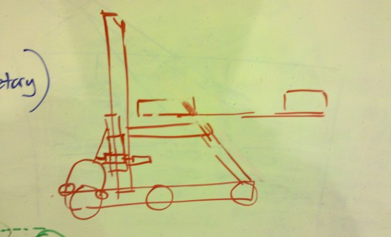
Space Claim Analysis Sketch for the robot. The minibot is housed on top of the horizontal elevator support and can slide out backwards to attach to the pole.
Next, we started to analyze what our tube grabber could be shaped like. We knew that one of the major issues would be getting the tube grabber over the bumpers to pick up tubes on the floor. To solve this problem, we thought about creating an arm that would come down from the elevator carriage and have a second roller below it.
A second issue we were worrying about was depositing the tubes on the rack. Our experience with the 2007 FRC game as well as the 2011 VEX game led us to believe that simply spitting the tubes out of the rollers could result in unpredictable scoring. To eliminate this issue, we thought about having the two rollers separate with a pneumatic piston so that the tube could be gracefully released and deposited on the rack in one fluid motion.
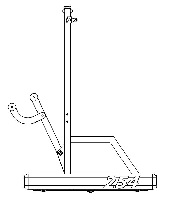
The Raised Tube Grabber. The grabber would be able to raise to perfectly vertical so that the tubes can be carried entirely within the volume of the robot.
We also talked some about the speeds for the elevator. We decided that we could use one BaneBots 775 Motor and one Fisher Price Motor on the spool gearbox to still leave enough motors for the rest of the robot. We decided to gear for a faster cable speed than either of the elevators we have built (for comparison, the 2007 robot’s elevator moved at 3.6 ft/sec and the 2011 will move at 5 ft/sec).
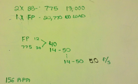
The gear ratios for the 2011 elevator. The first stage will use 32DP gears and the other two stages will use 20DP Gears.
Prototyping and Testing
We decided to build some prototypes to test how much force would be needed to keep the tube grabber closed. We built a jig to hold two wheels at a specific angle and allow us to apply force between them. It was found that with the tubes, once the wheels had passed the diameter of the tube, the frictional force was so great that the tubes could not be freed from the grabber.
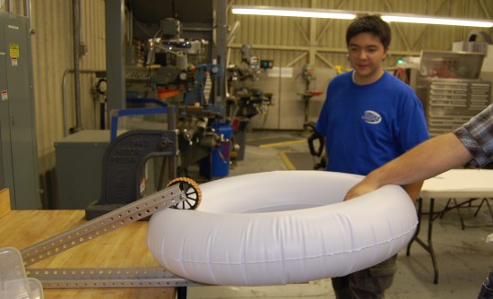
Testing using two wheels as a tube grabber. With static wheels, once the wheels pass the diameter of the tube, the tube cannot be freed from the grabber by pulling.
Another issue we addressed was the tendency for the tubes to rotate in the grabber. By putting a metal tube behind the tubes, it improved tube centering on most tubes. Problems, however, arose when testing on the corners of the square and especially triangular tubes.
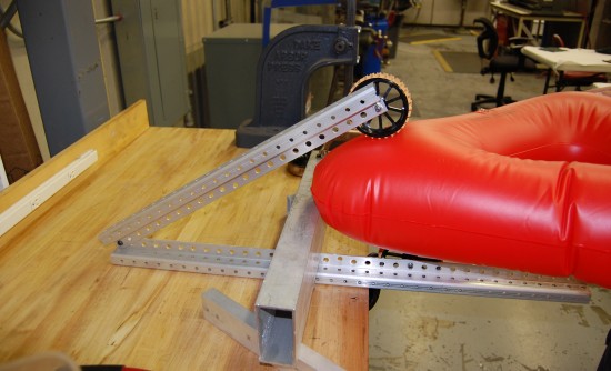
On the corners of the triangle, the wheels cannot get past the major diameter of the tube, causing more difficult tube retention.
To allow the tubes to still be held on the corners, we tried applying various amounts of force to the top of the lever. We found that after about 12lbs of force, it was extremely difficult to dislodge the tube from the grabber.
Manufacturing
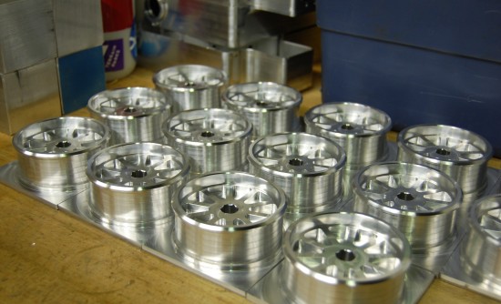
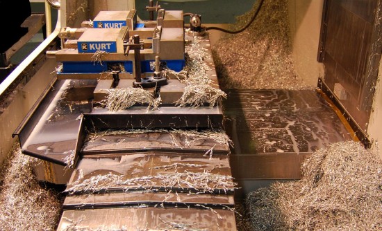
The machining of the wheels is coming along very well. The first operation is complete on almost all of the wheels. We hope to complete the wheels tomorrow.
Last year, we had an issue where the hole in the wheels created by the rotary hex broach was not big enough for the hex shaft. This year, we have purchased a new hex broach to fix this issue. The wheel fits very nicely on its shaft.

