Blog Archive
Robot Bagged
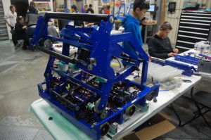
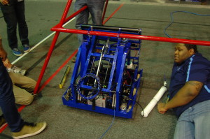
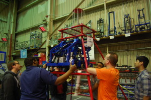
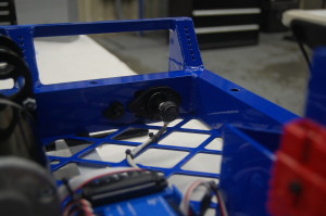
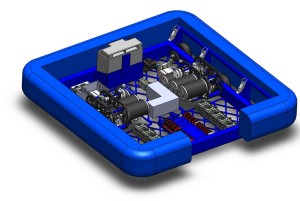
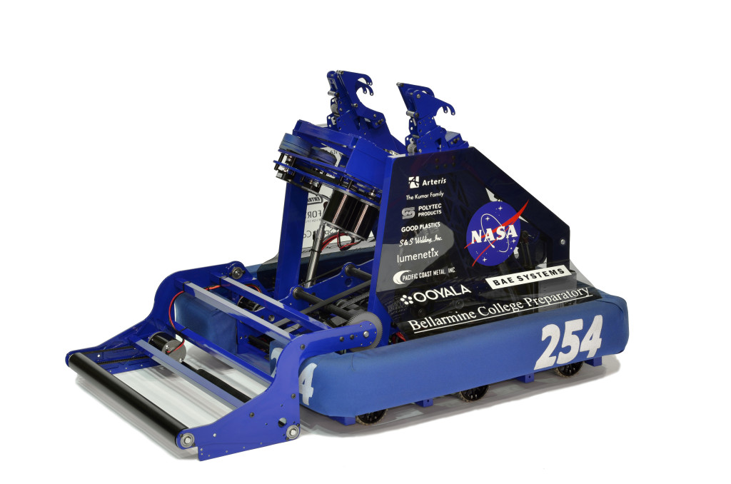 Today marked the end of the “official” build-season. The competition robot is enclosed in a bag and will stay there until our first Regional Tournament in San Diego (March 7-9).
I would like to thank everyone for their hard work, dedication, and support these past six weeks. Parents, thank you for the support you gave the students, by letting them come to the lab for such long hours, by providing meals, and by giving constant support. Students, thank you for your dedication to this project and your hard work. Mentors and teachers, thank you for your help, your relentless push to complete such a massive project, and your extremely long hours inside and outside of the lab.
That said, I want to remind everyone that build IS NOT over. Even though the competition bot is in the bag, there is still a lot to be done. There are many parts that need to be finished on the practice bot and many components need to be completed. There are subsystems that need to be iterated. With our first regional in two weeks, we will not be stopping build. We will be meeting at the same hours on the same days.
Tomorrow, February 20th, we will NOT be meeting. We will resume build on February 21st, at 5:30 pm. Rides to/from Bellarmine will resume on Tuesday, February 26th.
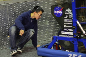
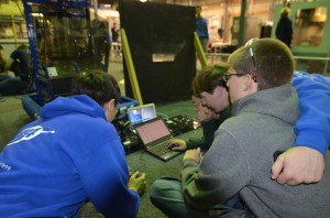
Below is a photo from tonight’s robot photo shoot. Please remember to keep any information and pictures about the robot confidential. Even though the official build season is over, we want to reveal the robot at our leisure prior to one of our first regionals. So please, keep all information confidential.
Thanks everyone for a great six weeks so far; we’ve come a long way (but still have plenty to go). Thanks and Go Poofs!
Day #40: Hang On Tight
Over the course of the past six weeks, robot development has come a long way. Today the team was able to test out robot hanging for the first time. That is a great accomplishment for the short amount of time allowed, but the robot still requires a great deal of work in order to be complete by tomorrow, Tuesday. In other words, mentors and students must make the final push tomorrow, just in time for bag-and-tag.
Wiring
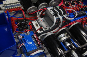
The team worked to attach most of the wiring for the robot. They wired the pressure gauges in order to fire pistons and hang on to the pyramid. Students also routed encoder wires to the shooter and other functions of the robot. Autonomous testing will be done soon after their completion.
Assembly
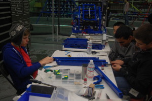
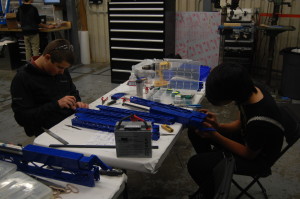
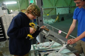
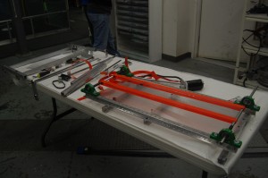
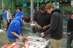
Students worked tediously to complete all layers and dimensions of the hanger arms. Because the arms must extend, they built linear sliders, which substantially adds to the complexity of its build. They deburred teflon blocks to mount screws, drilled holes to place screws, and assembled bearings for a smooth slide in and out.
Another group of students also cut and bent polycarbonate sheets for the bottom support of the conveyors.
Manufacturing
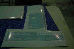
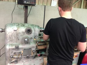
Students used the lathe to manufacture more spacers for the robot. Nagy designed, printed, and cut out the sponsor logos to put on the robot.
Programming
The programmers wrote code for all systems of the robot to facilitate testing of the competition robot. Besides this, students wrote a Notifier class that will publish events to each Listener, which will help with communication across the robot. For instance, if the shooter has detected that it has shot a frisbee, it will send a notification to Notifier; since the Indexer is a “subscriber” of the shooter’s notifications, it will know to load up another frisbee.
Meanwhile, the programmers continued work on TCP communication between the robot and a laptop.
Action Items
- Finish robot!
Expected closing time for the lab: all day and all night
*To all of the dedicated members that read this blog nightly, the lab will open at 9:00 AM Tuesday morning to finish the robot.
Day #39: Scrimmage Day 2
Lab Scrimmage
Today more teams arrived to the lab to use the field for practice, including 256, 751, 840, 1700, and 4535. The operators tested various shooting, climbing and driving mechanisms, as well as software.
Assembly & Wiring
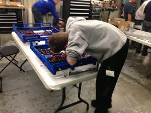
Due to a lack of space in the lower workbenches of the lab, students and mentors transferred the robot to tables in the upper deck, and worked on wiring the competition robot. In the lower workbenches, students worked on assembling the climbing mechanism, which will be later attached to the robots.
Manufacturing
Today, mentors and students machined shafts for the climbing mechanism on the lathe.
Programming
Most of the programming involved minor changes to ports and testing motors, Talons, and encoders on the competition robot.
Pit Lights
A few programmers tried to capture the signal sent by the IR remotes that control the new pit lights. Unfortunately, they could not get the Microsoft IR receiver or the Arduino to capture the signal properly. When they do, they’ll record the values corresponding to buttons on the remote and try to send those signals with the Arduino IR transmitter. This would allow a script to send data to the Arduino regarding which color to change the lights to. Ideally, we’ll be able to bypass the sensors altogether and send signals directly to the lights without IR.
Expected closing time for the lab: 7:20 AM
Day #29: Bumper Construction
Bumper
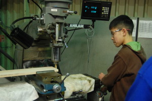
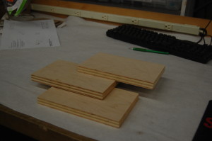
Over twenty students and two mentors collaborated on measuring and cutting the wood for the bumper. Students measured the bumpers to be 5" in height and lengths of 28.25", 28", and 8" for all of the sides of the perimeter. They then went outside to cut it with a miter saw. Students later brought the pieces to the mill to fine-tune the lengths to be precise. They will be assembled together next.
Milling wood frame to length
8" wood
Wiring
EJ and Jonathan Lee led other students to continue wiring on the drivebase. They then stripped, crimped, and soldered the encoder wires to the digital sidecar through PWM cables.
Encoders
Programming
Today, the programmers conducted more tests with the autonomous scripting command parsing. The team had a discussion at the whiteboard and talked about the sequence of excecutions of a mix of parallel and sequential commands in a CommandGroup. One topic that came up was the ability to treat a group of commands as one group that runs parallel to each other, and will not move on to the next command until all the grouped parallel commands were completed. However, it was decided that this logic should be used in the writing of the autonomous script, using a clever mix of parallel, sequential, and wait commands.
Meanwhile, students also implemented the Indexer class, which represents the system that grabs a frisbee from the intake and prepares it to load into the shooter. The indexer has two Solenoids as instance variables, and has getter and setter methods for the states of the two pistons.
Action Items:
-
Finish wiring the competition robot
-
Release more parts for manufacture
-
Mill pockets in bumper wood
-
Wire Pneumatics
Lab Closing Time: 12:30
Day #27: Superstructure
Wiring
The wiring on the practice bot was fixed because it was routed incorrectly and they were in the wrong ports.
Manufacturing
A large portion of the raw material for the superstructure was cut today. Some of the actual machining started which included drilling holes and tapping them so that they would be ready to attatch to the superstructer once it is ready. Some of the superstructure parts are being milled to length.


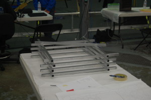
Completed super structure parts
Programming
Today, the programmers made miscellaneous changes and fixes to the 2013 code. The commands’ timeout functionality was changed to use the built-in setTimeout and isTimedOut functions, rather than creating an instance of a Timer and calling get(). This was tested and worked quite nicely and as expected. Additionally, the code was edited greatly to adhere to the style guide.
Day #24: Bumpers, Wiring, and Continued Prototyping
CAD
Students made some of the drawings for the conveyor shafts. The shafts with finished drawings should be finished tonight.
Manufacturing
Students manufactured a few of the shafts for the conveyor assembly. These hex shafts will used with the polyurethane rollers to move the frisbees from the intake to the piston-powered loader.
Manufactuing parts on the lathe
Bumpers
Students began measuring the dimensions of the bumper cordura based on the measurements of the robot bumper assembly in Solidworks. They will order 4 yd x 60 in cordura material from Seattle Fabrics for the red and blue bumpers. Particular effort will be spent making sure that the colors are according to the team standards. After confirmation of all details, they will place the order.
Wiring
Wiring today consisted of soldering connectors onto a mini CIM motor and another set of connnectors for the speed controller to test out the intake prototype. The students discovered that the motor’s shaft was spinning, while the gear was not. After some modificaitons, the team was able to successfully control the speed of the intake with the speed controller, which was mapped to the Logitech gamepad.
The current drivebase chassis
Prototyping
Students continued design on the intake, revising the polyurethane rollers as well as the polycarb on top. This wasn’t worked on much today, but the improvements drastically increased efficiency.
Student making adjustments to the intake
PR
Students continued to revise Chairman’s as well as work on various sponsor things. Awards will be delivered later this week, and prospective sponsors are being contacted.
Programming
Today, the programmers continued work on tuning the PID controller for the shooter wheel. The results were roughly about the same as yesterday’s results. When the actual shooter is built, the team will spend a great deal of time to tune the shooter controller very nicely and accurately. But for now, this was a good exercise and experience the team can learn from. The programmers are currently experimenting with a mix of filters, different controllers (bang-bang vs. PID), and feed-forward.
Meanwhile, other programmers wrote code for the intake prototype. They mapped it to the Logitech gamepad, so that the shoulder buttons would increment or decrement the speed controller output by 0.005, the start button would set it to 0.0, and the back button would set it to +1.0. This functionality was requested by the students working on the intake prototype, since they want to find the minimum required torque to intake a frisbee smoothly. Tests are currently being conducted on this.
Programmers intently programming
Day #21: Conveyor and Stuff
Conveyor
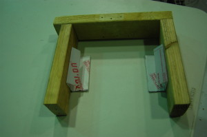
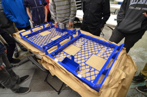
Today, students worked on the conveyor system. This is the part that will transfer the frisbee from the conveyor to the shooter. The frisbee is pressed into the polycarb, where it gets stuck due to two 30-degree hinges. Students first created an 11 x 11 inch box, then labored over the polycarb to get it just right, and finally unscrewed one of the sides of the square, creating a U shape.
Day #19: Reconstructed Intake
Prototyping
Intake
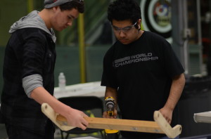
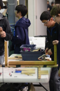
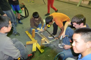
Students continued to make modifications to the intake prototype. They scrapped the entire aluminum model because they decided it would be too time inefficient to drill and redrill holes into metal. Instead, the team constructed the front of the robot frame and the intake prototype with wood. A life-size drawing of the intake arms was printed out and glued onto a wooden block. Then, the intake arms were cut out with the vertical bandsaw along the traces.
In addition, shafts were manufactured on the lathe for the intake prototype. The team plans to have the intake mechanism fully designed and tested by Saturday, or Sunday at the latest.
Students assembling an intake prototype with wood
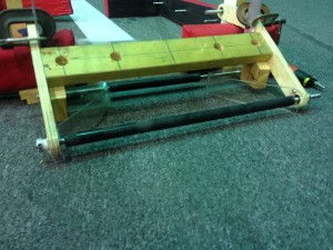
At around midnight last night, the team decided to remove the vertical rollers and add a bottom roller. This resulted in a much simpler two roller design which worked really well. The front roller is still 25″ long, while the back roller is 12″ long. Students also added passive polycarbonate funnels on each side so that the frisbee is in the center by the time it hits the roller.
Intake with bottom horizontal roller
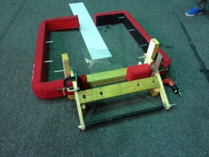
Intake attached to wooden bumper frame
Meanwhile, students also created a wooden bumper frame out of wood to mount the intake mechanism. Like the new wooden intake, a wooden frame would allow the team to more easily drill and make modifications to the prototype.
Creating wooden bumper frame
Programming
Sensor Testing
The programmers had a very successful day. They began by bringing in and testing two additional VEX ultrasonic sensors from the VEX lab. Upon testing, the students found that one of the additional sensors was significantly better than the previous single ultrasonic sensor. The better sensor can detect surfaces of a distance greater than 12 inches, whereas the old sensor could only detect up to 3 inches. Though the VEX ultrasonic sensor works when tested with the shooter prototype, the team is still exploring other sensors as ways of detecting the orientation of the frisbee.
Testing the three VEX ultrasonic sensors
Control
The programming team traveled upstairs for a group programming session, using one single laptop and a projector. The students worked together to implement a Controller class and reimplement WPILib’s PIDController. Instead of having multiple threads for each of the controllers, the team created a way to update each controller in one thread. This was done by making the Controller class and abstract class that held onto a static Vector of Controller objects. Then, in the constructor of the Controller class, “this” controller would be added to the Vector. Finally, a method called updateAll() would iterate through the Vector to update all of the controllers. This was a breakthrough moment for the programmers, as a solution utilizing fewer threads would make the whole process more light-weight.
When this new code was deployed to the 2012 robot Skyfire, no exceptions were thrown and no errors seemed to pop up. Miraculously, the code worked flawlessly on the first try!
Action Items
- Continue assembling intake prototype
- Reimplement and commit state space controller class
- Add conveyor to intake prototype for the purpose of constraining the frisbee in all directions.
- Prevent frisbees from getting stacked once they were through the intake
- Turn down front roller to 3/8″ so that it can be driven with the pneumatic drill
- Model new intake in Solidworks
Lab closing time for the night was 2:30 AM
Day #18: Powder-Coated Parts
Prototyping
Intake & 2010 Robot
Students continued to develop an intake prototype, now attached to Onslaught, and the intake will be completed as soon as possible. However, due to the arrival of the chassis, students removed Talons from Onslaught to be placed on the new drive chassis. This transfer means that we do not know which robot (Onslaught or Skyfire) that the drivers will practice on, but Onslaught will still be used for testing sensors.
Manufacturing
Today, GIlbert Spray Coat returned the powdercoated chassis a day earlier than expected, and students began working on putting electronics onto the frame, such as the power distribution board, ten Talons each, digital sidecar, the Spike relay, the power switch, and solenoid. Additionally, Pacific Coast Metals returned other anodized parts, such as gearbox plates and spacers.
If the shafts are returned from Modern Machine Company tommorrow, work on assembling the gearboxes will begin. However, there are a few missing parts that still need to be aquired. The 40T gears, shifting dogs, shifter shafts, and a few other parts from West Coast Products are still missing.
The bearing housings were received from Pacific Coast. Mentors and students worked on pushing the bearings into these housings
The two powdercoated chassis
Programming
Today, the students spent most of the time trying to make a VEX ultrasonic sensor work on an FRC robot, in order to determine the orientation of a Frisbee. Most of the time was spent debugging the sensor, as the sensor was returning arbitrary and random values. The programmers discovered that the two port numbers should be switched in the code, which made the ultrasonic sensor work. However, during testing, the sensor seemed to be able to detect surfaces a maximum distance of around 3 inches away. This is a problem, as the VEX ultrasonic sensors are designed to be able to detect distances of up to 115 inches away. The team thinks that interference from the surroundings could possibly affect the sensor’s abilities, but more tests and debugging will be done tomorrow to get to the root of the problem.
In addition, a couple of the robotics laptops were transfered to the lab for programming use; however, the nature of the Bellarmine servers prevented work from being done on the laptop. Currently, the team needs to reinstall the wireless card driver on the laptop.
Action Items
- Debug and test ultrasonic sensor
- Continue working on the intake
- Continue adding electronics to the chassis
- Continue designing the shooter, climbing mechanism, and intake
- Start wiring
Day #14: Prototyping, Programming and Designing
Prototyping
Shooter
The shooter protoype is coming along as students worked to test an added polycarb cover. To test the effectiveness of smaller wheels on the shooter, a group worked on replacing the treaded wheels with Banebots wheels. Tests proved favorable for the treaded wheels.
Intake
Leaders and students continued to test the intake system. Tests utilizing a single roller intake have proved successful. Students added an elevated mount to mimic the path that the frisbees will have to travel in order to enter the robot. Tests in intaking multiple frisbees have proved successful and steps are being taken to improve on the design.
Intake with wooden stands
Programming
Driver Station
Students progress by printing messages from the robot to the driver’s station control board. The programmers worked on some code to allow the driver’s station to cycle thorugh different autonomous modes. The “Y” button on the Logitech F310 joystick was mapped such that while the robot is disabled, a driver station user message line would display the current autonomous mode. This ended up working quite well with the available commands the team had already: drive distance and wait.
Meanwhile, the team also took time to strip and crimp a five-wire encoder wire into two female PWM terminals. This would allow the programmers to plug the S5 encoders into the digital sidecar to test the team’s S5 encoders. Unfortunately, this has yet to be completed; testing will occur tomorrow to ensure that both the wiring and encoders work.
Writing the autonomous mode selector
CAD
Bumpers
Through diligent work by students the CAD for this year’s bumpers are nearly complete.
Drivebase
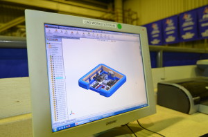
Students and mentors have continued to work in Solidworks to design our robot’s drivebase. Progress was made by adding electrical components to the CAD to map out the distribution of speed controllers, CRIO and pneumatic systems placement, and the power distribution board.
The design of the robot drivebase in Solidworks
Action Items
- Test S5 encoders
Day 10: Shooter & Programming
Shooter
The shooter retained most of its current form in terms of design, some new pieces were just added on. A system for indexing and stacking frisbees was designed and implemented on the prototype shooter, so that it will be able to load several frisbees.
Programming
The programming team had an effiecient day today. Firstly, they worked on the autonomous script and selector. The programmers hope to cycle between hard-coded and on-the-fly autonomous sequences with a press of a button. Secondly, they worked on the Smart Dashboard and the GUI. The team managed to get the FTP connection to work. It turns out that the Apache Commons jar should be placed in the lib/ directory of the Smart Dashboard folder. This has yet to be tested on the driver station laptop, which will be done tomorrow. Finally, they started designing the control board and creating the corresponding list of parts. The team decided on driver and operator controls, such as joysticks, buttons, and switches for the robot's functions. Students also decided on the sensors that would go in the robot (encoders, gyro, etc).
Design
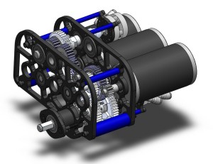
The design of the robot has been coming along slowly but steadily. The team decided on a 6 motor drivetrain utilizing 6 CIM motors. Furthermore, each drive gearbox has a Power Take-Off (PTO) which could be used later to power a hanging mechanism.
After intake prototypes illuminated potential difficulties bringing disks up such a steep angle, it was brought up that a wider robot would allow for a gap in the bumpers for frisbees to travel through. After a long discussion, this route was pursued and the drivebase weldment (assembly 254-13-A-0300) was finalized and the base plate was sent out for manufacturing by sponsor BAE Systems.
With the drivebase weldment finalized, students worked to make CAD drawings for the components of the weldment. Furthemore, the control board design began.
Miscellaneous
The shipment from Coast Aluminum arrived. It was taken apart, checked and stored with the other aluminum. Some of it was cut to begin manufacturing a few of the smaller parts.
Action Items
-
Finish bumper design
-
Hold a design review for the helical conveyor/indexer
-
Begin prototyping the helical conveyor/indexer
-
Begin cutting drivebase stock
-
Continue work on autonomous selector
-
Test uploading files from Smart Dashboard on driver station laptop
Day #9: New Intake
Prototyping
Shooter
Students have made a couple of modifications to the shooter prototype. An L channel was added, in addition to guide rails. A pneumatic piston was attached to the shooter to load the frisbees into the shooter wheels.
The goal was to make a shooter that could shoot frisbees both upside down and right side up. After making the modifications and adding the "autoloader" the shots became more consistent (because of the same loading dynamics). However, the upside down shots and the right side up shots were aiming differently. The most significant difference is the flying dynamics. The upside down frisbees were more unpredictable and didn't fly as well.
Students making enhancements to the shooter
Conveyor
Not much was changed on the conveyor. Upon the completion of the shooter and intake, students will integrate the conveyor design with the two other prototypes.
Conveyor prototype
New Intake
The team took a new route with the design of the intake. They removed some of the orange polyurathane belts in the process. A new intake was constructed from the CAD. Though it works fairly well, the team is working on improving it. It can't quite take two frisbees at the same, but can still pick them up quickly. The design is based on the old conveyor prototype and old intake prototype.
At the end of the night, the intake was fully functional and was able to funnel two frisbees into one. It was also able to easily pick up the frisbee from the ground, albeit not as well as was hoped. The intake so far is not fast enough and not consistent enough. More work will be done on it tomorrow.
Building the new intake
Programming
The programmers worked on a Smart Dashboard widget for writing constants and their values to a text file, and uploading them to the robot using FTP. They first worked on the layout of the widget, and were successful in the writing and clearing functionalities. However, the programmers still had issues creating an FTPClient object and connecting to the robot.
Dorian Chan programming the Smart Dashboard widget
Students also wrote a Turn Command for use during autonomous mode. The ScriptedAutoReader was configured to read the word "TURN" as a TurnCommand and appropriately create one. It seems to work, but the command still requires extensive testing, since the command depends on the gyroscope and the robot was left on the stand.
Richard demonstrating turning in real life
Miscellaneous
The pyramid was fixed. The top goal of the pyramid was brought down for some adjustments, and then reattached.
Fixing the pyramid goal
Action Items
-
Continue work on intake (make it work)
-
Make shooter accurate
-
Do math, save world
Lab closing time for the night was 2:00 AM
Build Season Begins
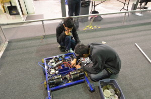 The team is now a week into the short 6 week FIRST Robotics build season. We've made a ton of progress on everything from design and prototyping to field construction and programming. We have built the pyramid from the field drawings and have come up with a ton of concepts for various game challenges, some of which have been tested. The programming team has been working to get old robots up and running both for programming practice and for testing prototypes.
The team is in agreement that Ultimate Ascent, this year's FIRST challenge, is one of the harder games in recent FIRST history. However, we're happy with the prototypes that we've been working on and are confident that we'll be able to pull together a robot to play the game.
Team 254 works on a different schedule than many other FRC teams, designing and manufacturing parts in parallel. This forces us to design sequentially and finalize parts as soon as they are ready so they can be made in time. For example, some robot parts were designed on day two and sent out to sponsors on day three of the build season.
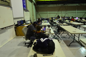 As we move into week two, the focus is on continuing to prototype designs and trying to lock down some aspects of the robot design so that we can send more parts out to sponsors by the beginning of week three. It'll be busy but we think we can do it.
Day #7: Drive Base and Talon Testing
Prototyping
Intake prototype
Students continued to improve on the Intake prototype. We wanted to have the Intake prototype powered by one CIM motor. We designed a system which utilized timing belts, gears, and an intermediate roller to power both the top and bottom rollers of the Intake. This is currently still a work in progress
Intermediate conveyor prototype
The team continued to refine the conveyer prototype. The team started out by opening up the new polyurathane belts that came today, and proceeded to brainstorm on how they could improve the conveyer. The team decided on three things.
- Improved belts
- A Compression device to hold the frisbees in
- Counter Sunken Screws in said compression device
Improved Belts
The old system continued to have slippage with the timing belts, and thought the new polyurathane belts would solve this issue. The team cut the belts to the correct length, fused them together, and stretched them over the place where the old belts were.
Compression Device
The compression device solved the issue of the frisbee slipping off of the belts. The compression device consists of a piece of polycarb which has been sanded down for reduced friction. The polycarb is drilled down 1.3 inches above where the frisbee sits, holding it to the belts
Counter Sunken Screws
The new compression device posed a new problem, screws sticking out of it, holding the frisbee back from free movement. The team solved this issue by using a technique called countersinking, where a divet is drilled around the area of the screw, allowing it to rest out of harms way. This completely solved the issue of the frisbee getting stuck.
Shooter prototype
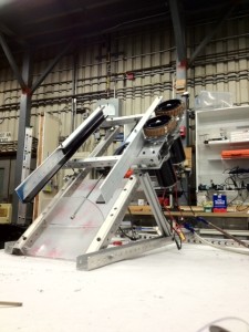
- The 1×2 tubing was replaced with 1×1 tubing in order to raise the wheels higher so that they would contact the disc in an upside down orientation.
- The length of the bottom plate was increased to increase consistency when loading the disc
- The left side wall was shortened to try and make the discs go straight instead of off to the right.
- The stand for the shooter was improved such that it sits flat without being held down.
- Shooting upside down was very inaccurate because even with raised wheels, the wheels still push the disc up. U-channel needs to be added on both sides to keep the disc in line.
- With the shortened left side wall, the discs did not fly straight, they flew to the right. With U-channel added on both sides, and past the wheels, the discs should fly straight as they exit the shooter.
Programming
Then programmers updated the 8-wheel 2010 drive base to work with Talons. It will be used to mount the prototype intake and shooter. The team also made the robot controllable with the Logitech gamepad. A few members and mentors drove the robot around the field with the new controller. There is no new progress on the constant file reading system nor the autonomous command system.
Tomorrow, the programmers will work on the autonomous command system, the gamepad controls, and constant file reading.
Lab closing time was 12:30 AM
Day #4: Success with Intake and Shooter!
Today was a huge improvement in student attendance over yesterday. With our first active weekday build, a majority of the time was spent designing and beginning initial prototyping of an intake mechanism.
Prototyping
Intake Prototype
Students worked in a group to brainstorm ideas for an intake mechanism that will allow the robot to take in discs from the ground. One of the several ideas brought up include horizontal rollers to roll the discs in. However, the orientation of the disc (facing upwards or downwards) and friction between the carpet and the disc are challenges. Currently, one new intake prototype has been constructed that can take in discs on the ground from either orientation.
Students brainstorming ideas for the intake
Shooter Prototype
Additionally, some students are continuing work on manufacturing parts for shooter prototypes.
One new shooter prototype that is under construction is a linear shooter, powered by two wheels. One wheel will be powered such that it is faster than the other.
Manufacturing parts to build a shooter prototype
Testing Prototypes
Some students are using the drivebase of the 2010 robot, Onslaught, in order to test shooting and future intake prototypes. Currently, there is a problem with power to the cRIO, which prevents controlling or deploying code to the robot. Once the 2010 robot is up and running, the team will attach prototypes to the robot to test out prototypes on the field, while driving.
Drivebase of the 2010 robot, Onslaught
Programming
Reading Constants
The programmers discovered that original idea to use Java reflection will not work because the robot uses Java ME (mobile edition), which does not support this feature. They brainstormed some other possible solutions including using a hash map for storing variables read from a file, but it is likely unfeasible due to its heavy computational expense. Another idea is to use a flat text file with constant values that can be transferred to the robot without re-compiling and re-deploying code.
Controls
In addition, the programming team tested out a Logitech game controller as a way of driving the robot. The analog sticks on the controller were successfully used to control the drive. More comparisons and tests between joysticks and the game controller will occur later on in the season.
Action Items for Tomorrow
-
Fix the wiring to the cRIO on the 2010 robot; flash new image to cRIO
-
Work on and test prototype for intake
-
Work on and test linear shooter prototype
Lab closing time for the night was 12:30am
Day #3: Design Discussion
Today was the first weekday of build and with fewer member attendances, there was a lot of individual work getting done. Majority of time was spent in conversation between students and mentors on design decisions.
Prototyping
Three different designs are continuing to be prototyped:
- Arm design
- Started installing a longer piston
- Increase range of motion to have greater spin
- Extended arm length
- Linear Design
- Wood bottom plate removed because of warping
- Bottom plate replaced with metal bars to reduce bend
- Added electrical tape to increase traction
- Adjustments made to effectively improve consistency
- Radius design
- No work was done on the radius design today
Design
Mentors and students continued designing the robot baseplate and the drivebase in Solidworks. The drivebase was completed before Nagy lost all his work. It will be completed tomorrow at school.
New discussion outcomes:
- 32″ x 24″ frame
Additional testing
Students began to install 4 new Talon speed controllers on the 2012 robot Skyfire drive motors to replace the Victor speed controllers. Later on, the Talons will be tested and then based on results, the team can decide which speed controller to use for competition.
Programming
The programming team worked on implementing a trapezoidal motion profile to accompany PID control, which involved quite a bit of math. Meanwhile, other programmers continued working on a way to read constants’ values from a text file, and update the constants accordingly. Tomorrow, we hope to make adjustments to the code to use Talons instead of Victors, and test drive the 2012 robot.
Action Items for Tomorrow:
- Finish drivebase CAD (restore Nagy’s lost work)
- Continue Prototyping
- Add support for Talon speed controllers in code, test, and compare with Victor speed controllers
Lab closing time for the night was at 10:30pm
FRC Season Day #1: Kickoff
After the whole team kickoff-unveiling event at BCP, students came to the NASA lab at 1:00pm to begin discussing game strategy, going over the new game rules in detail, and began numerous design, prototyping and field assembly tasks throughout the course of the day. Prototyping A couple of groups were created which began making prototypes to test the fundamental concepts of shooting Frisbee discs. A few objective requirements that are being looked at in these designs include:
- Accuracy
- Precision
- Size/Volume occupied
- Power requirements
- Design integration ease
- Feeding/indexing/loading ease
- Need for adjustability
Three different designs are currently being prototyped:
Radius Design
- This design is very similar to this YouTube video
Radial Design
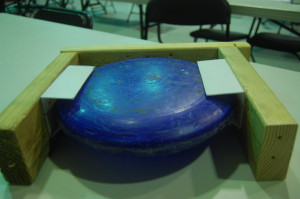
- The radial design uses a fixed wheel spinning on an axle surrounded by a circular track for a frisbee. By doing this there it simultaneously adds speed to the frisbee using the rotating wheel and spin using the far wall of the track that is padded with self-insulating electrical tape for increased grip.
- We used many different iterations of motors starting with Dewalt drills, but opted for more power using pneumatic drills running off shop air spinning the wheel at 5250 RPM.
- Using the higher RPM we were able to semi-accurately shoot from 10ft away from the high goal.
- A working prototype was created and tested today as shown in the video above
Linear Design
- This design is an iteration of the Radius design, but packaged more tightly to accelerate the Frisbee disc linearly, instead of around a radiused backboard
- The idea was created as a derivative of the Radius design, coming from the need for a compact shooting mechanism. Utilizing the same idea of a static surface combined with a spinning propellant, we designed a system that uses a direct mounted CIM motor to power a timing belt pulley system to increase speed of the frisbee in a single linear movement.
- CAD models of this design were completed and fabrication was started today
Thrower Arm Design
- This design is most similar to a clay pigeon device
- The main mechanism of this design is a flinging arm that propels the frisbee as it travels from the center of the device towards the outer most edge
- Fabrication of this design was started and photos will be added when a preliminary model is created
Design Preliminary design decisions were briefly discussed regarding drivetrain configuration, wheel size, and speeds/ratios. Final drivetrain decisions and preliminary designs for some drive components will be decided and completed at tomorrow’s meeting. Gearbox and wheel shaft models and drawings are scheduled to be completed by Sunday night, to deliver for manufacturing at our sponsor on Monday morning. Preliminary discussion outcomes:
- 6WD with 3.5″ Wheels
- 2-speed WCD (West Coast Drive)
- ~2011 speeds (with the capability to swap in a smaller pinion to go slower)
- Flat base plate
- 2011 style bumper mounts
Field Construction Students began working on building and assembling the high goal and the pyramid field objects. The High Goal stand was completed and mounted onto the game field. The assembly of the pyramid is underway, with its top goal almost complete; all components are made, but still need to be assembled together. 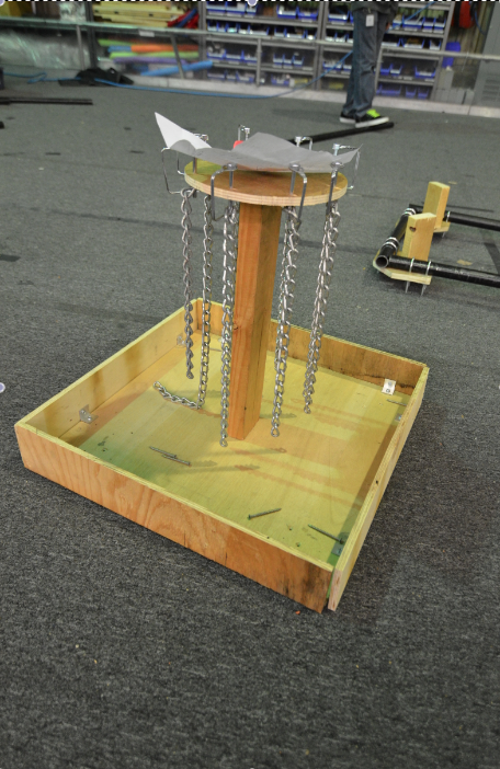 Manufacturing Final machine set-up and warm-up procedures were completed today which should allow us to start machining competiton parts tomorrow. Action Items for Tomorrow
- Acquire missing pyramid parts, assemble pyramid base and goal, assemble pyramid.
- Complete linear Frisbee shooter prototype & test
- Begin intake design and prototyping discussions
- Start and complete drivetrain gearbox designs and shaft drawings
- Discuss merits and perform objective analysis/ranking on hanging mechanisms & feasibility
Lab closing time for the night was at 12:30am
Team 254 Helps out at Toys for Tots
On Saturday December 22nd, 27 Cheesy Poofs came together to help needy children in the Santa Clara Valley. The members donated over 70 hours to help distribute gifts to the needy and bring smiles to their faces. The boys were painting faces and hands with Christmas scenes, running games with prizes, cooking hot dogs, distributing food and demoing Skyfire to the delight of all ages. This is the 25th Annual US Marines Toys for Tots event at the Fairgrounds and it was expected to reach 7,000-9,000 children.
SIA Awards Dinner
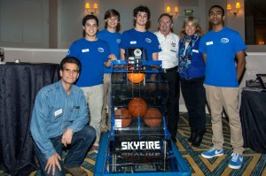 Last Thursday night, Team 254 attended Semiconductor Industry Association’s 35th Annual Awards Dinner, where we met Dean Kamen, spoke about FIRST, and spread the message of STEM.
We were lucky enough to be invited to SIA’s 35th Award Dinner and Reception, where we talked about FIRST, STEM, and the Cheesy Poofs. The event was hosted at the Fairmont Hotel, and gathered many prominent people in the engineering community together. Dean Kamen, the founder of FIRST (and creator of the Segway) spoke, as well as our mentor, Travis Covington. Our drive team, Abhi and Chris, spoke about the more mechanical topics, while Nagy and I spoke about how the game works, how the team is run, and how we interact with sponsors. Overall, the night was a huge success, allowing the Poofs, Bellarmine, and FIRST to be exposed to an amazing set of people. It was a night that will definitely be remembered.
Members Avery Strand, Abhi Kumar, Chris Sides, Nagy Hakim
Mentors Travis Covington, Ann Roemer
Calgames – Happening Now
This weekend, Team 254 is competing in the 12th annual WRRF Calgames Offseason Tournament. Watch the webcast of the tournament here!

