FIRST Robotics Blog
Day 31 – Rest Day
Today was another rest day. Have a weld video or two as we begin week 5!
Day 30: Machining, CAD, Game Elements, and Drive Base
By Clay Rosenthal
Machining
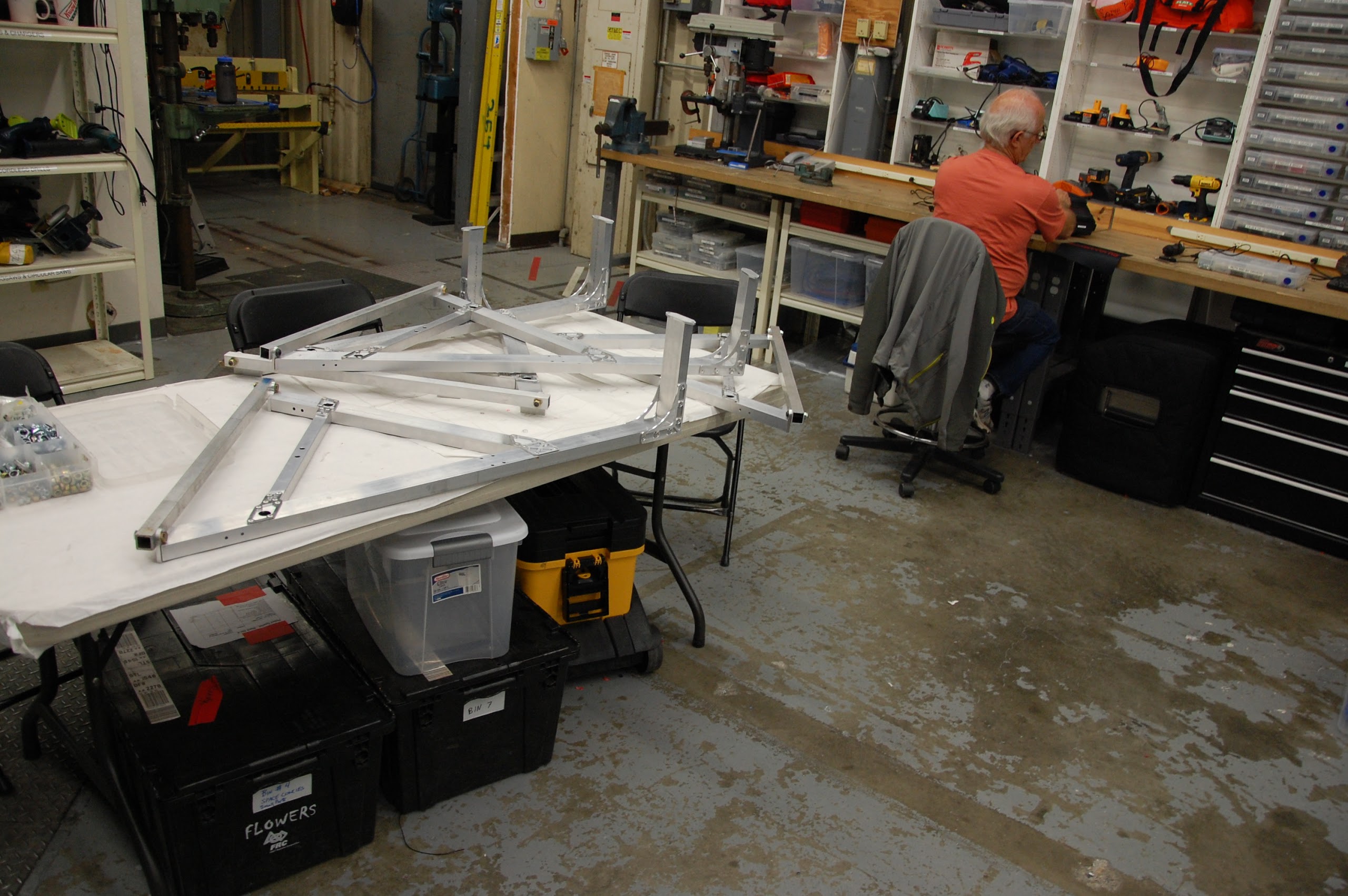
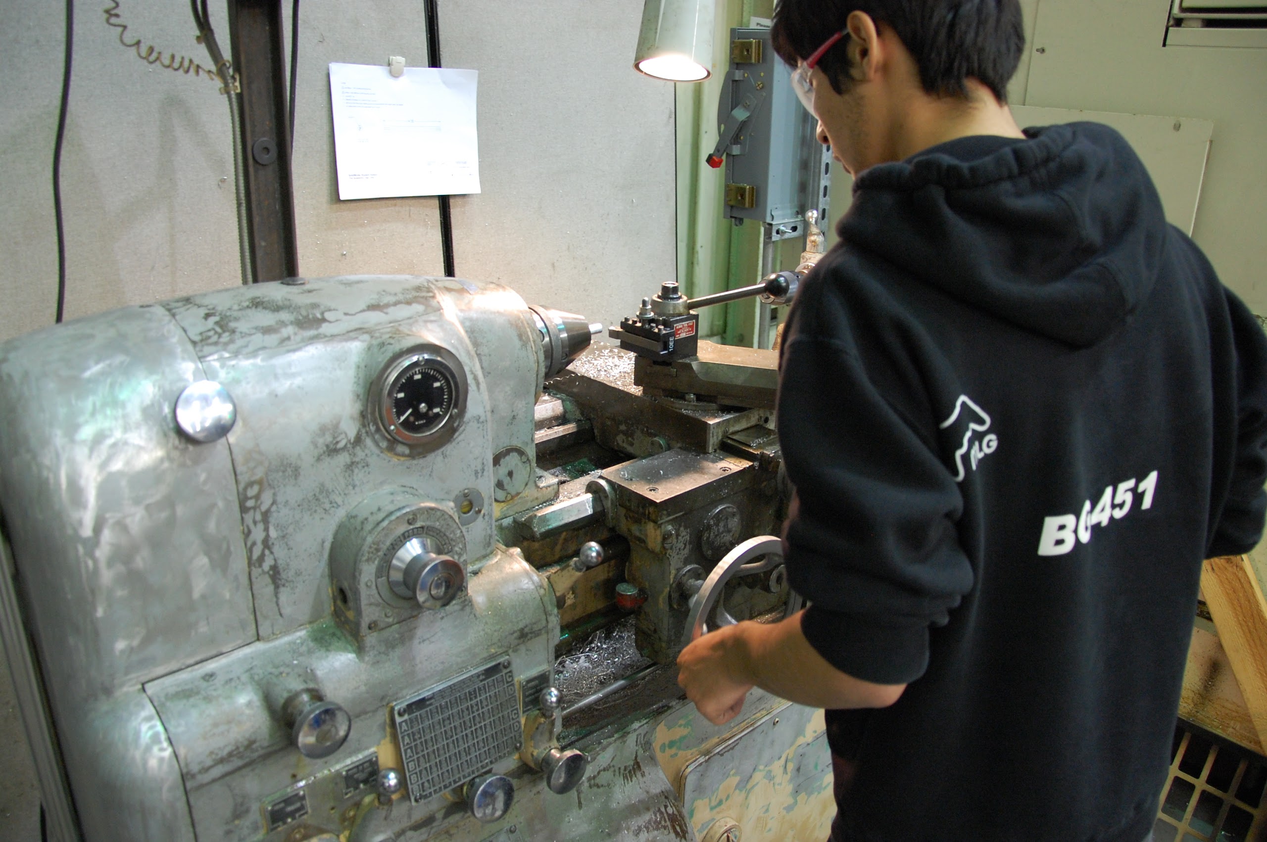
Parts of the superstructure were made today to be welded tomorrow. Parts to hold the pieces in place while being welded were also machined. The superstructure will be welded and powder\-coated soon. The parts for the hood and rear intake were also assembled and will soon be welded and prepped for powdercoating.
CAD
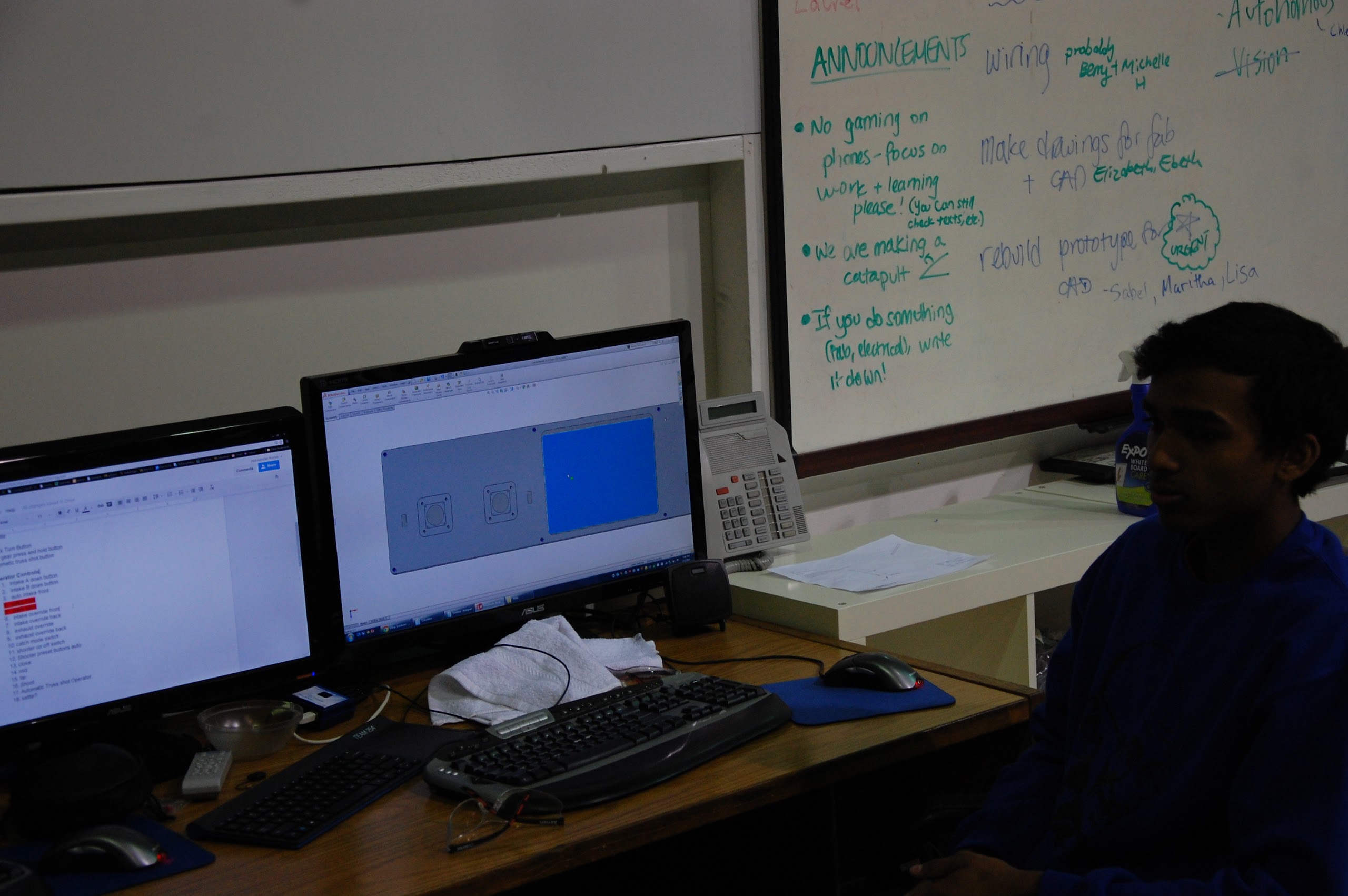
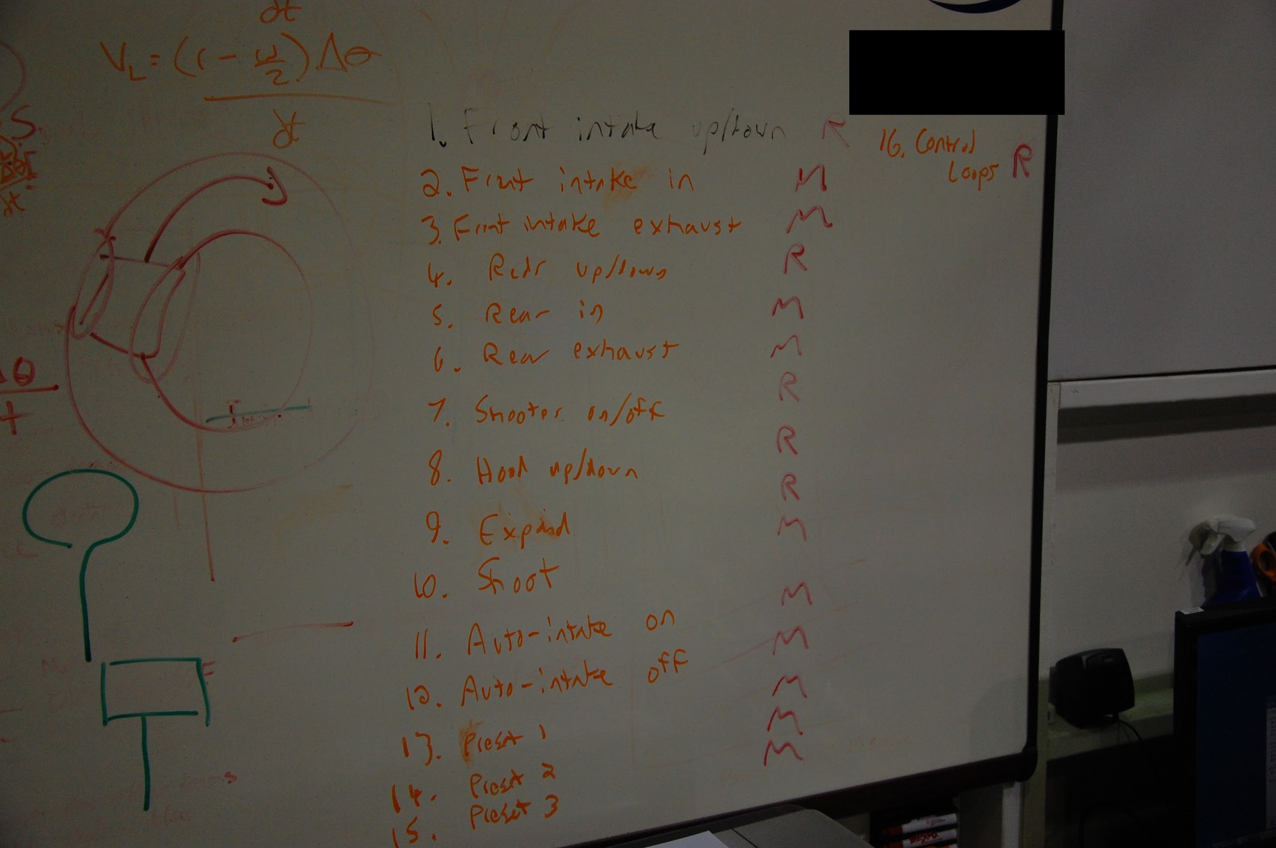
The clapper design was worked on today and is nearing completion. Locking pistons for the hood were also conceptually designed on today. A new control board with sixteen buttons is being designed. The buttons are described below \(‘R’ stands for rotational, or a switch, and ‘M’ is for momentary, or a button\).
Game Elements
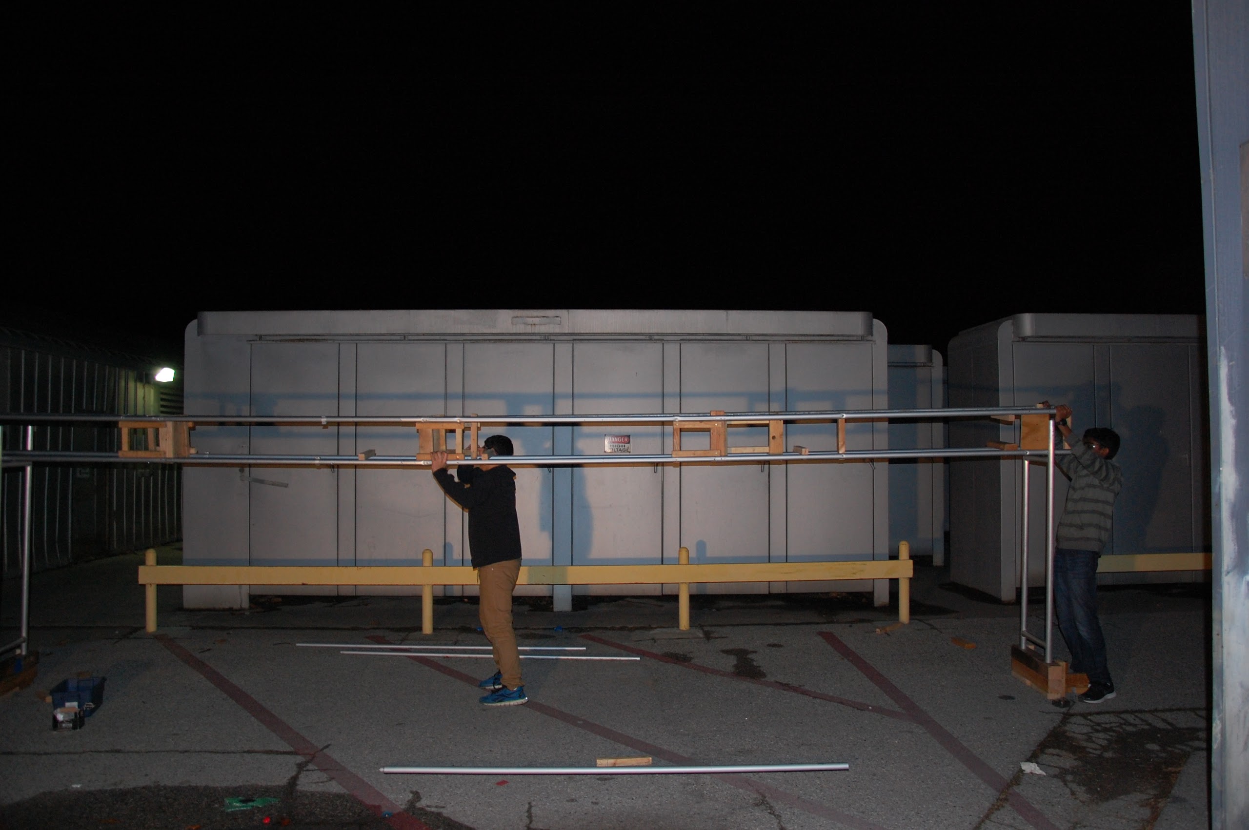
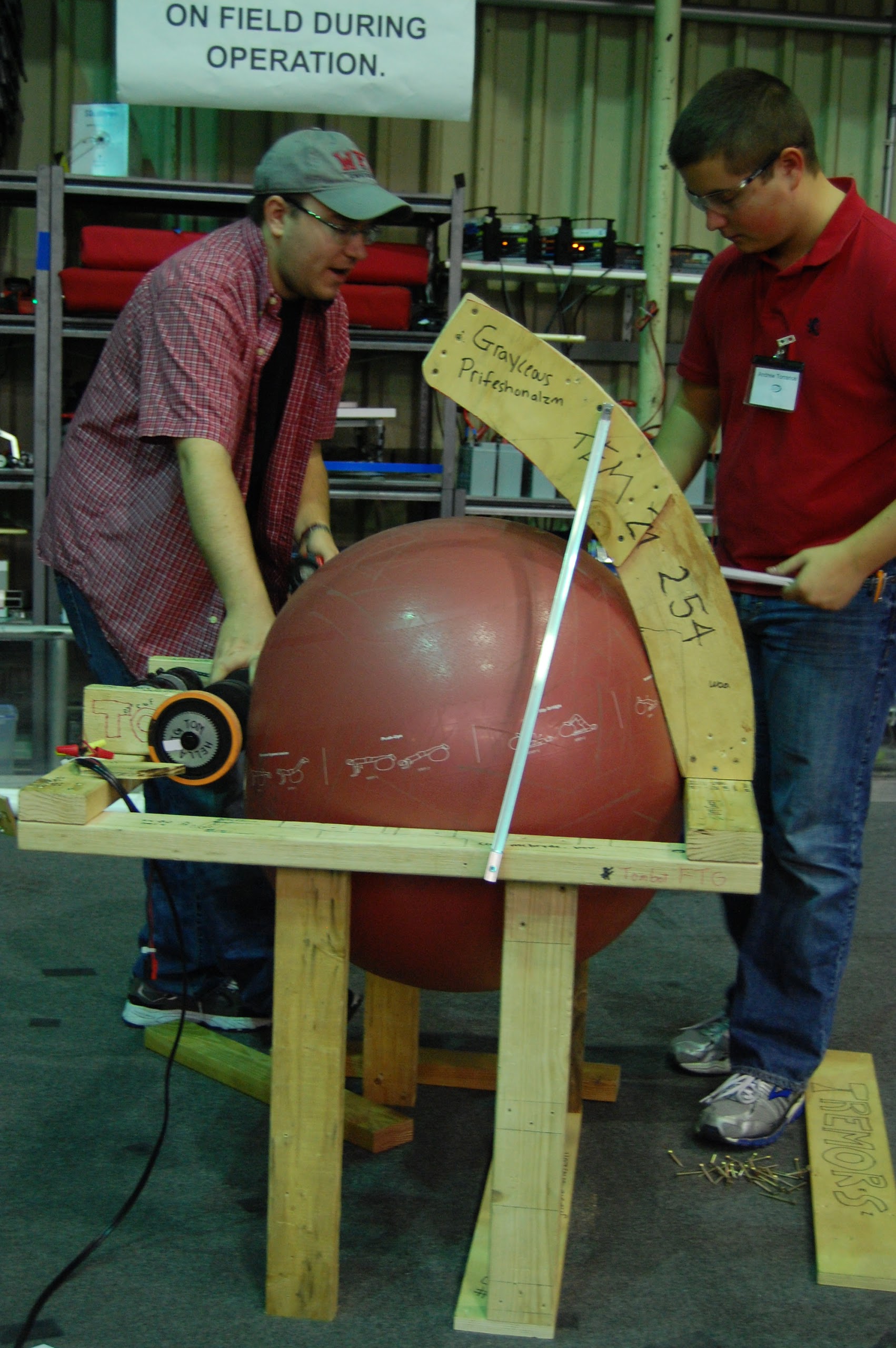
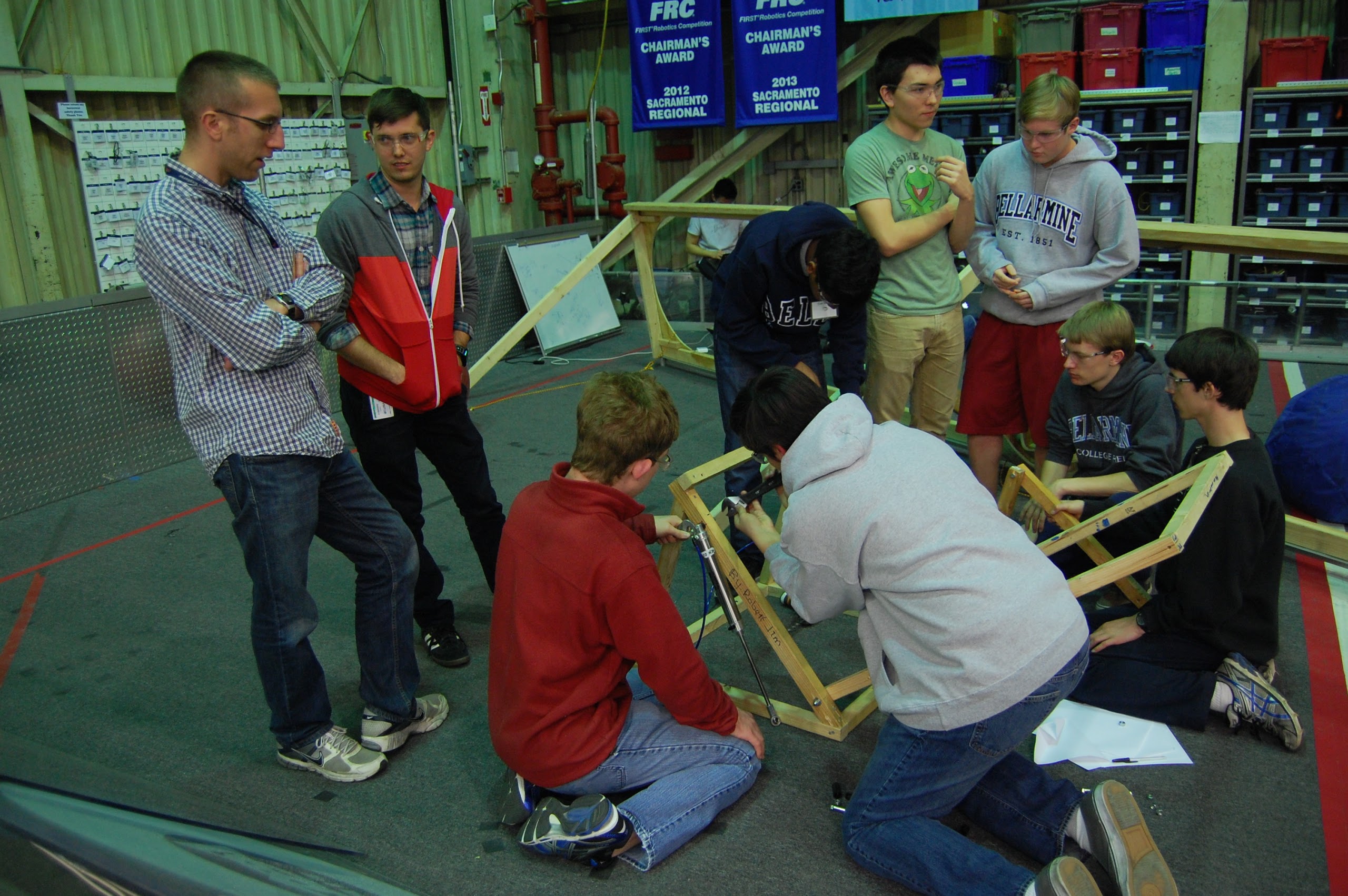
The truss was worked on more today and is nearing completion. It is standing tall but still bending. The two halves from yesterday were attached together. It hasn’t been hung over the field yet and is still being completed outside.
Drive Base
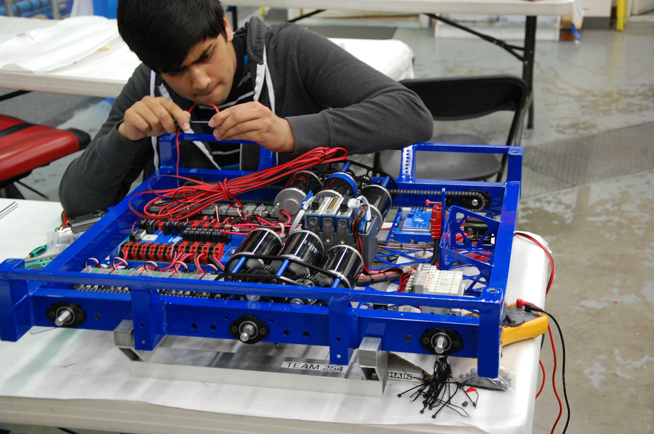
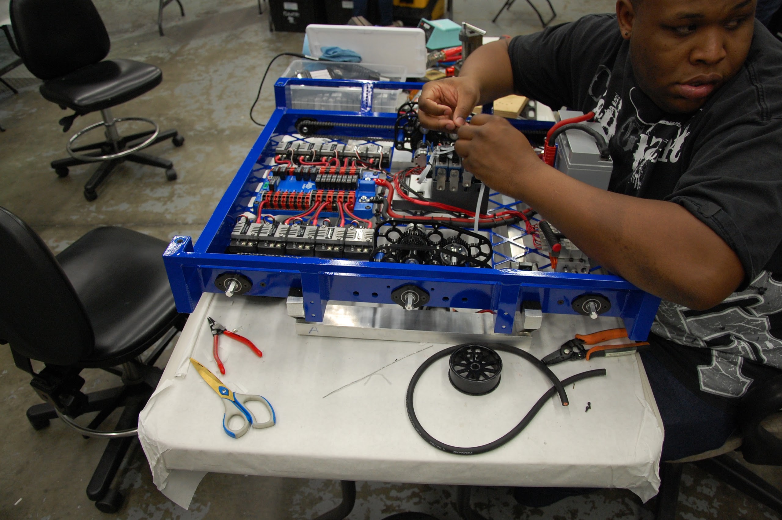
The competition drive base was wired and is pretty much ready for driving. The practice drive base is not far behind. The wheel axles now have chains attaching them to the gearboxes and the gearboxes on the practice drive base have CIM’s on them. New CIM’s have been ordered and will be put on when they arrive.
Action Items
- Wire andersons and drive gearboxes, Ask Mani
- Wire practice robot, Ask Mani
- Get everything ready to be welded
- Machine parts for hood, shooter, and intake gearboxes, ask Pat
- Finalize design for clapper, ask Colin
- Finish parts for shooter, hood
- Machine gearbox plates and piston mountsWire andersons and drive gearboxes. Ask Mani
- Wire practice robot. Ask Mani
- Get everything ready to be welded
- Machine parts for hood, shooter, and intake gearboxes, ask Pat
- Finalize design for clapper, ask Colin
- Finish parts for shooter, hood
- Machine intake gearbox plates and piston mounts
Day 29: Assembling Gearboxes
By Michael Simeon, Matthew Tran, Christian Bagamaspad, Stephen Pinkerton
Machining
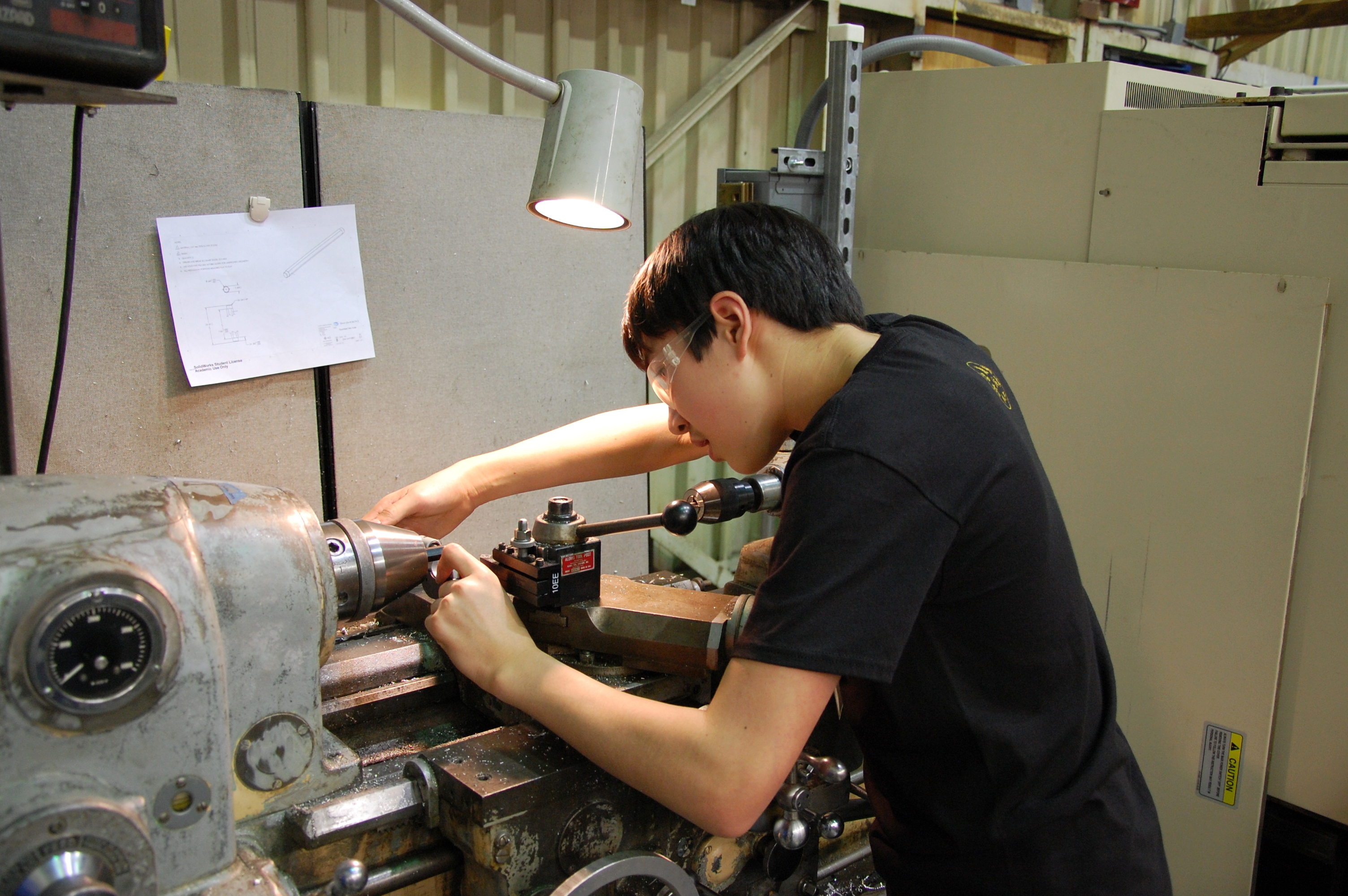
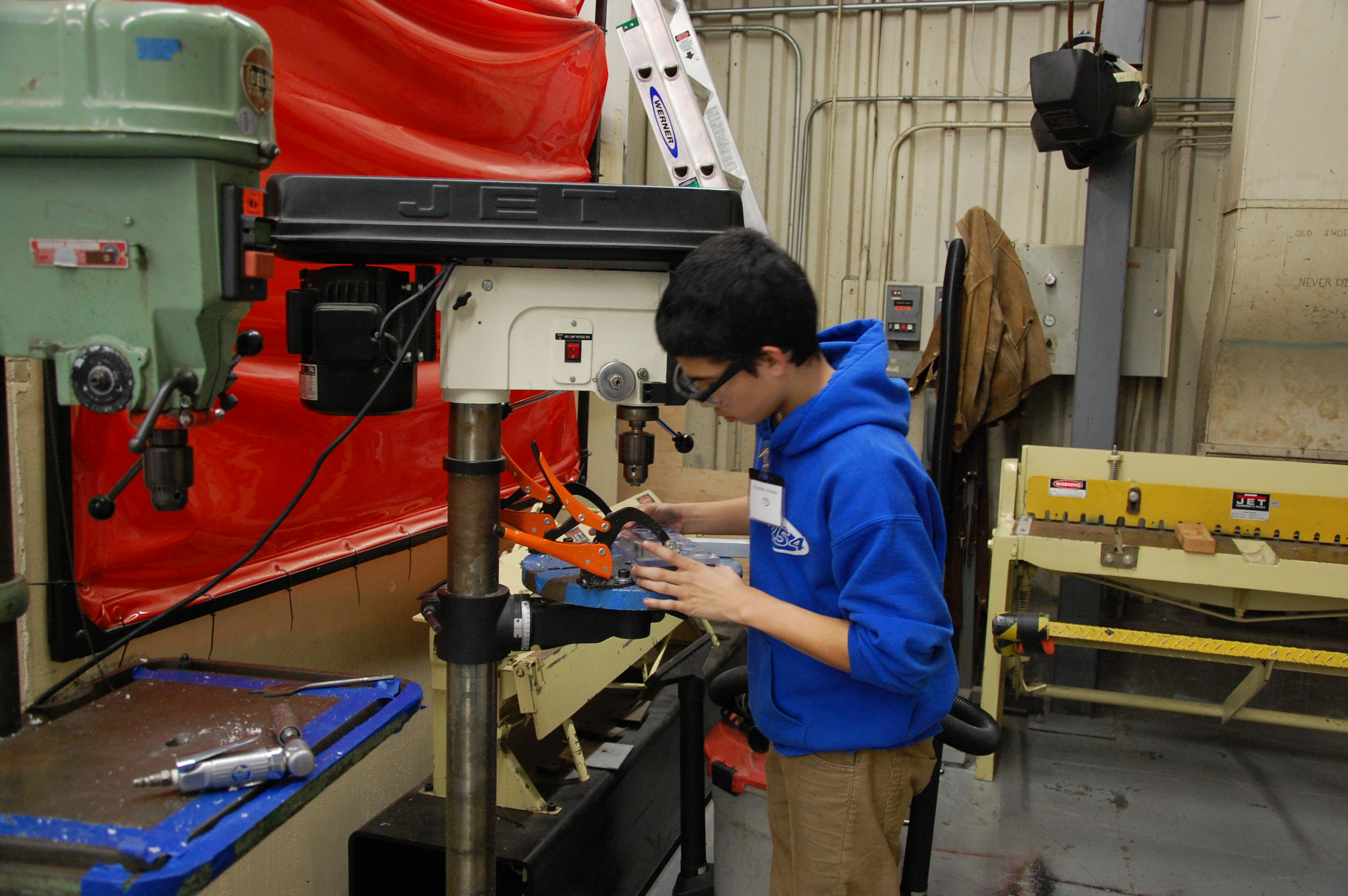
Today, members manufactured shooter shafts, standoffs, spacers for gearbox, and crosspieces for “seal.” Additionally, they began detailing and manufacturing parts for the front and back intakes.
They also machined parts for the hood weldment assembly, which still need to get welded. Most of the other hood elements are still being designed.
The superstructure parts are done and ready to be welded. Part of the hood attachment still needs to be CNC’ed before sending items to the welder on Monday.
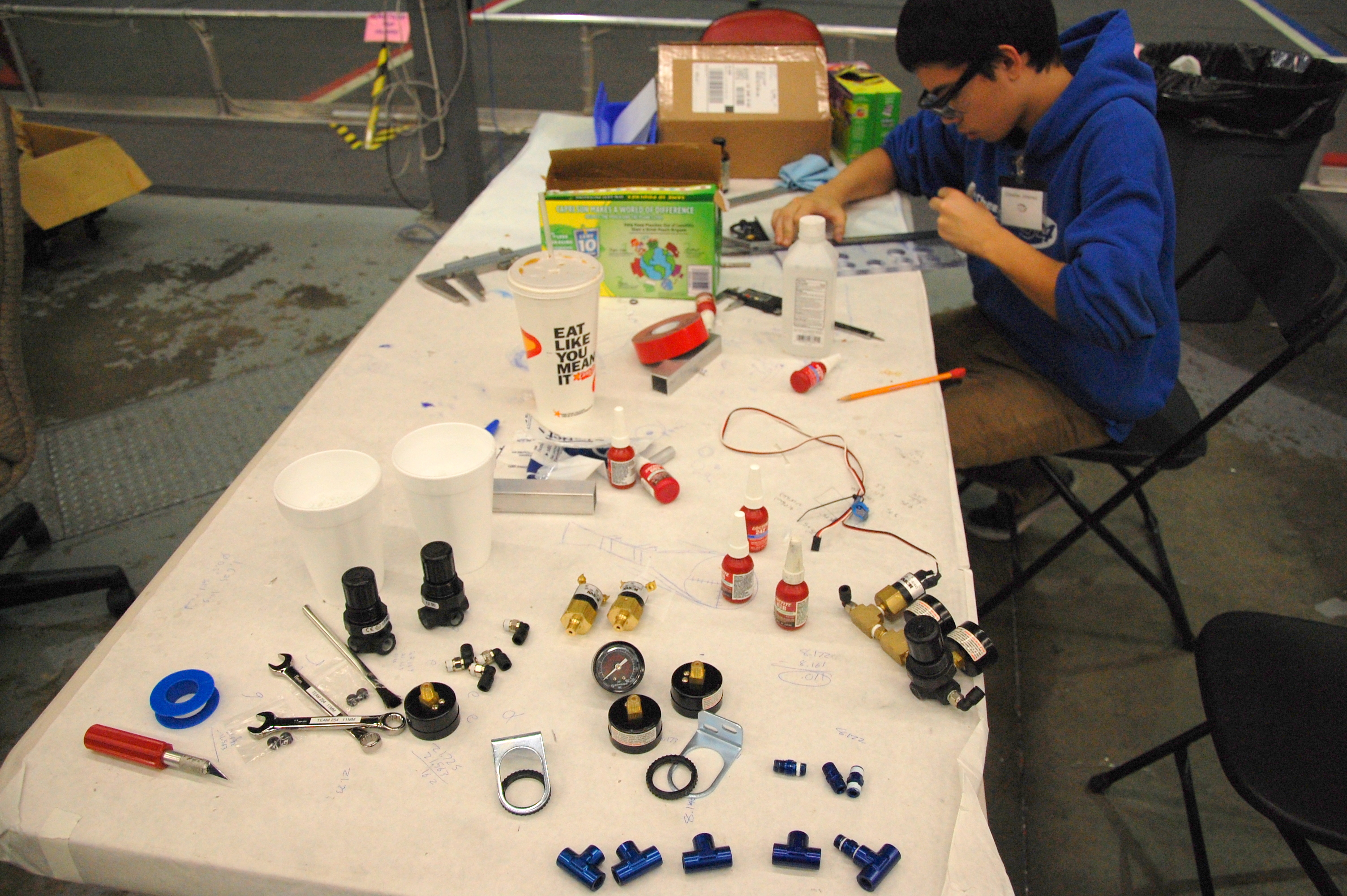
Gearboxes
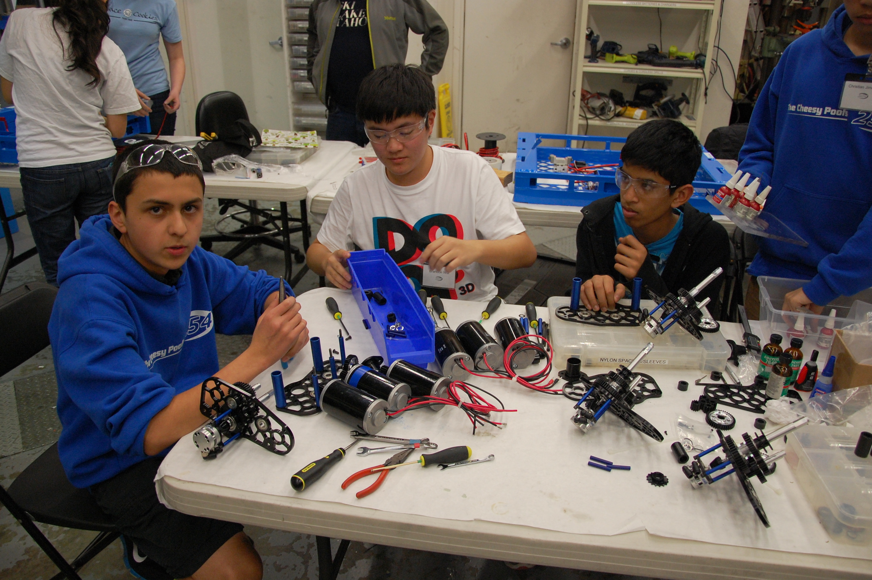
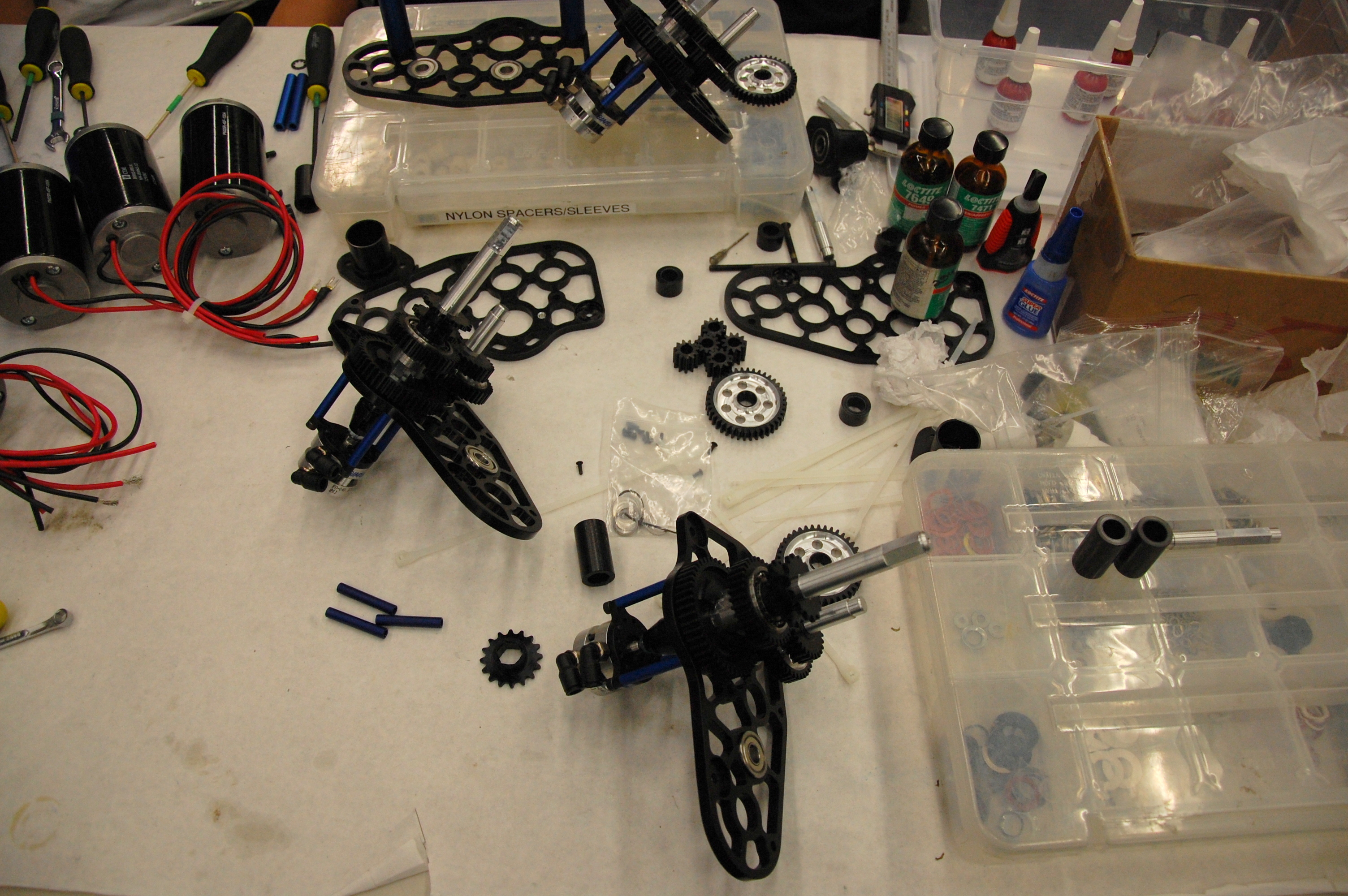
Members also assembled gearboxes, replacing long standoffs with shorter ones. There were some issues after assembling them the first time where bearings didn’t fit properly. These issues were mostly resolved after assembling them again, but more carefully. There may be more issues with spacers that we need to investigate tomorrow. All in all, only 2 of the 6 gearboxes have been assembled \(the ones for the competition bot\).
Wiring
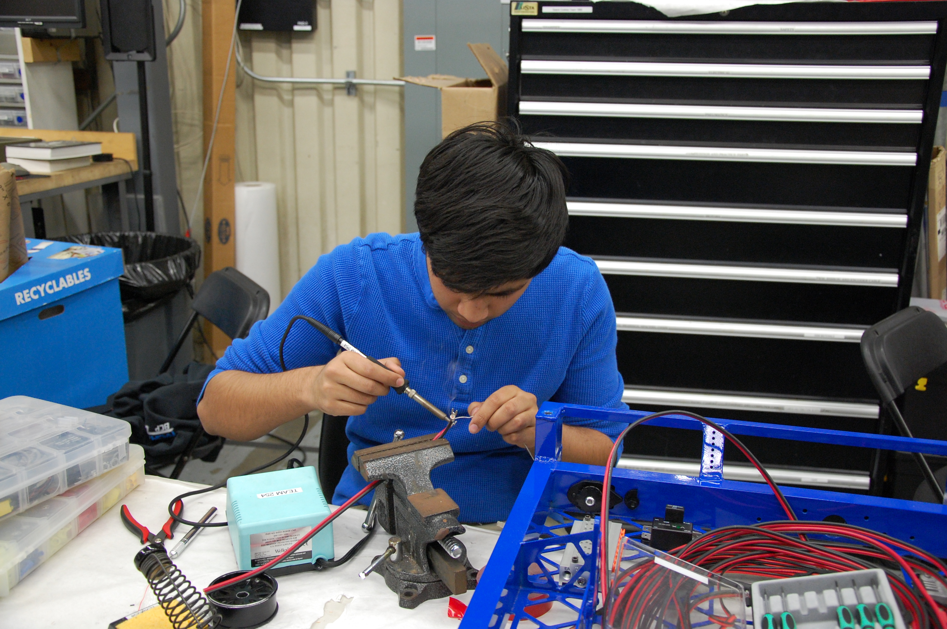
We started wiring late into the night and are being careful to do it accurately. The goal is to have this done very soon so we can continue driving.
CAD
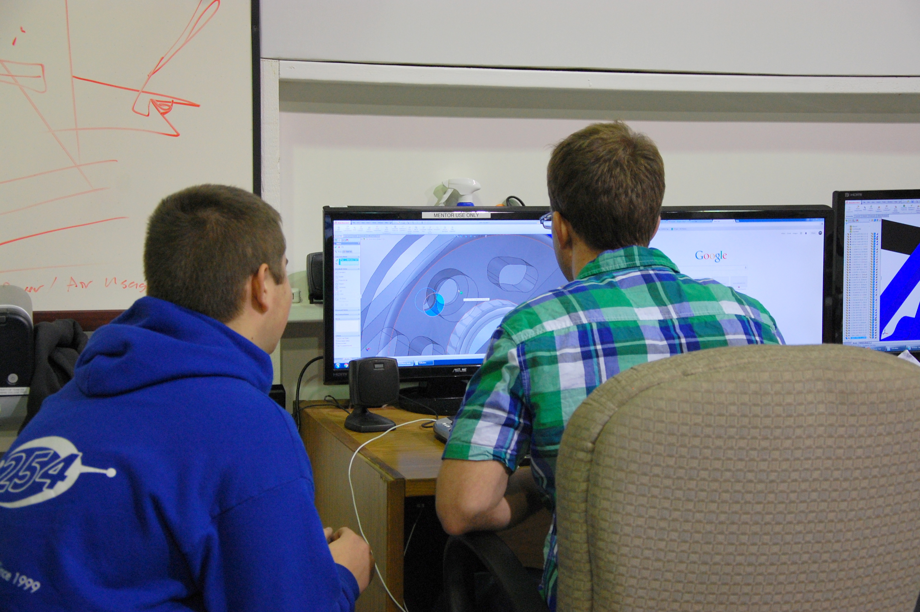
After successful testing the v\-shaped popper, the team decided to go with the prototype, and are currently designing it in SolidWorks.
There was significant work done on the shooter and hood CAD. Members added more detail, as well as some shafts, spacers, and screws.
Programming
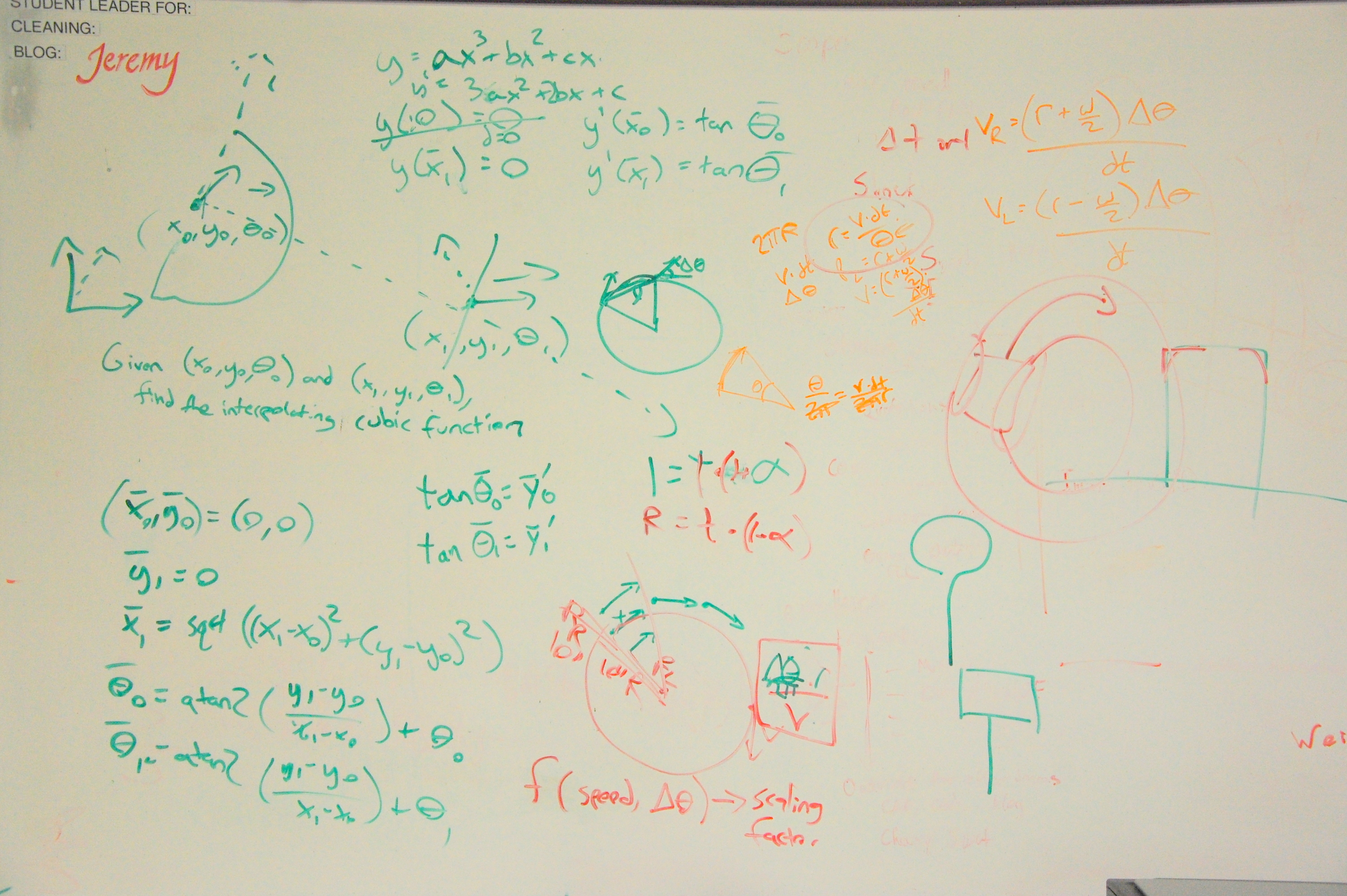
Today, the programmers worked extensively on cubic spline interpolation and trigonometric calculations. The purpose is to be able to turn smoothly and accurately. They implemented the calculations in a new Java project called TrajectoryLib, complete with unit testing. By the end of the day, they ironed out most of the bugs, and have not yet tested the code on the robot.
Moving forward, they’re looking to create a live position\-tracking page for the robot.
Graphic Design
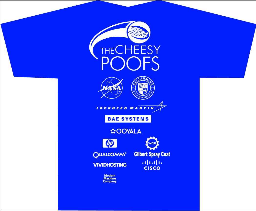
Today, some students made progress on the official team shirt for this season by trying a new design based on the Aerial Assist logo. They also incorporated the logos of our current sponsors.
Game Elements
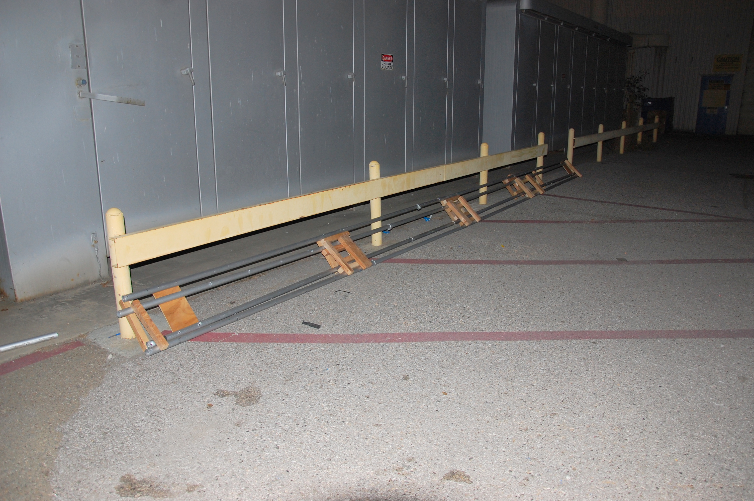
The team assembled a homemade truss \(instead of purchasing the official game element or buying actual trussing, which would take more than a week to ship\). Unfortunately, it is not completely sturdy and bows in the middle. It has not been hung up across the field yet.
Action Items
- Check Trello!Wiring drivebases
- Continue designing hood
- Debug and test turning code
Day 28: Coming Together
by Brandon Wui ’16, Christian Jimenez ’16, and Joncarlo Avila ’16
Machining
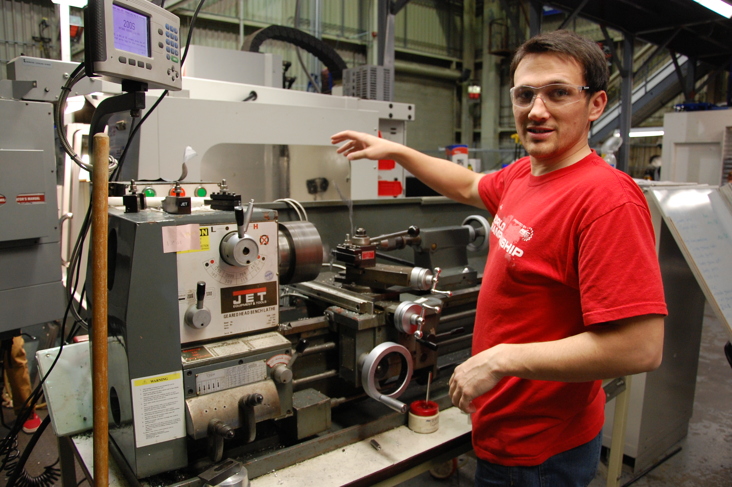
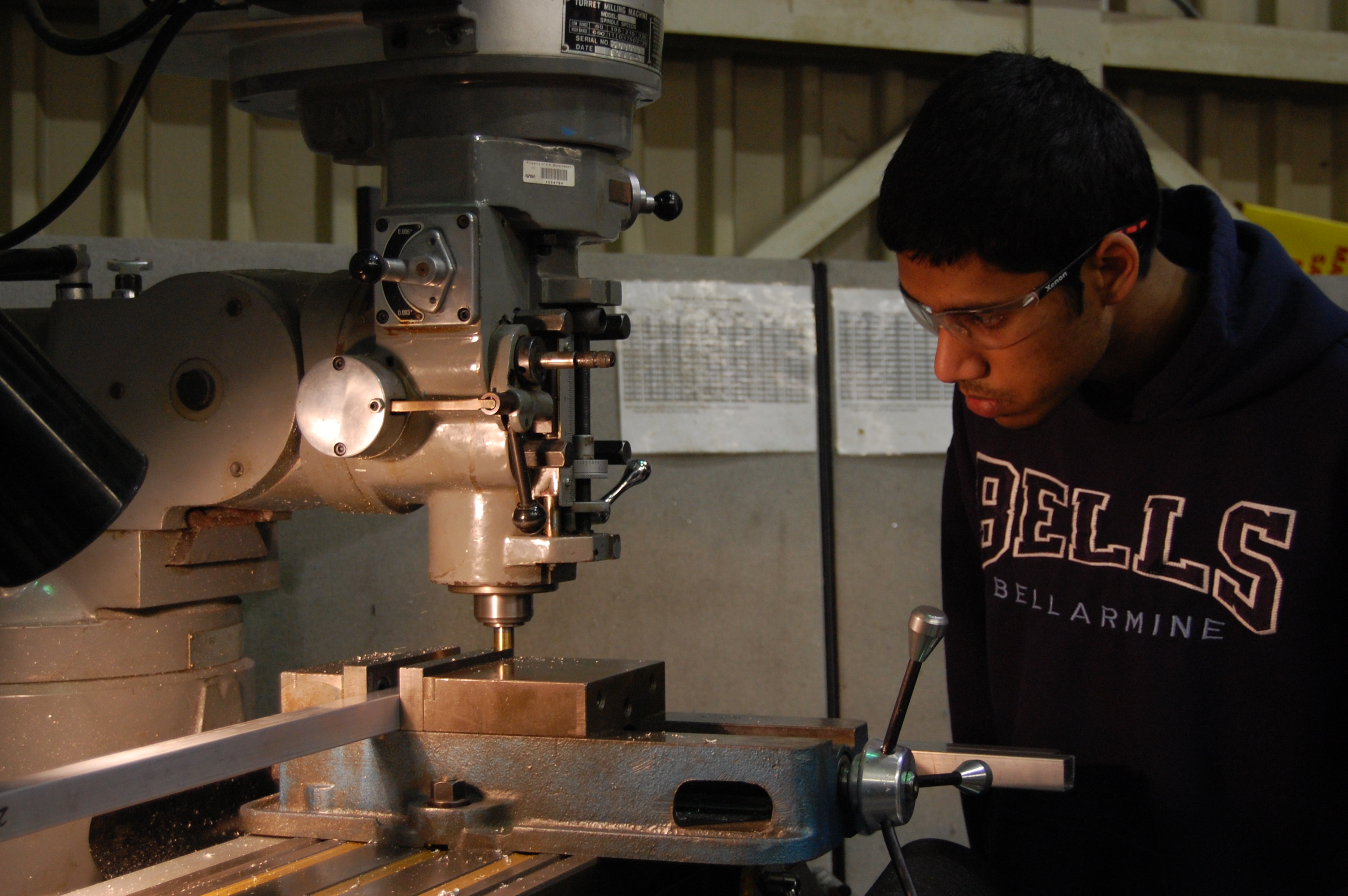
Today students machined parts for the intake and frame. They also worked on the lathe and band saw to cut pieces and face them for the superstructure. Finally, they drilled all of the holes based on the CAD model.
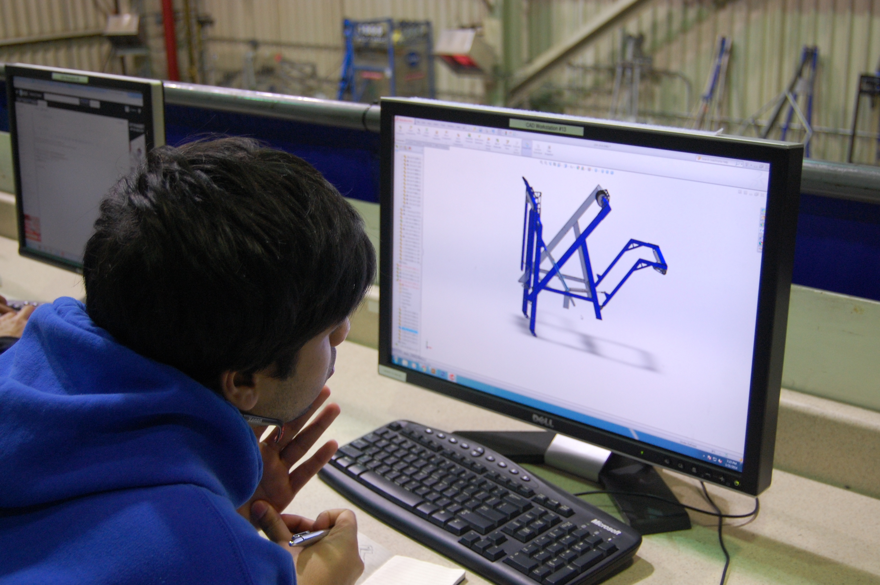
CAD
Today students attempted to add the hot goal sensor to the robot but could not find a good mounting spot. In addition, they updated the shooter design.
Awards Submissions
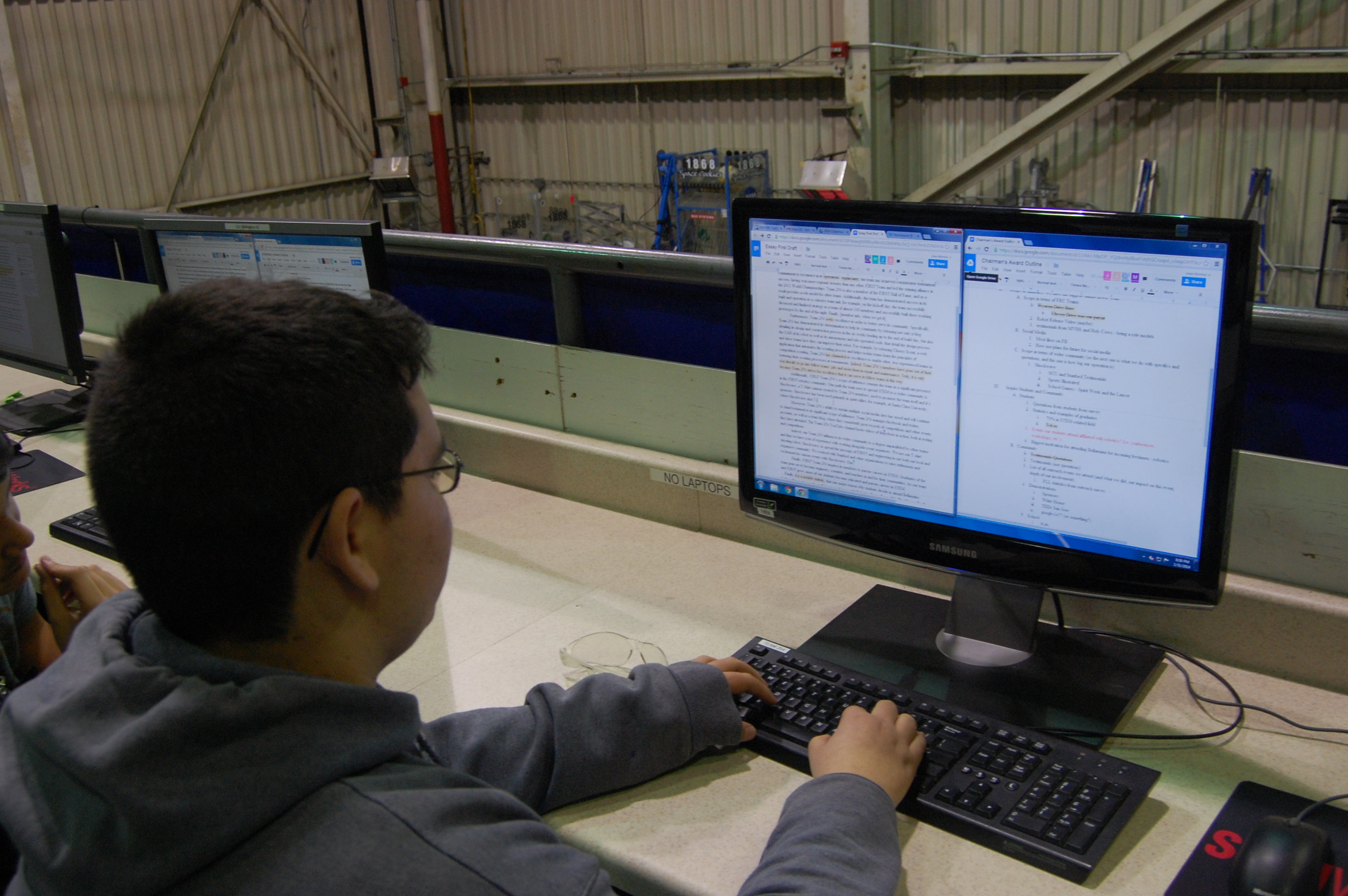
A group of students worked on the Chairman’s Award Essay. The outline is complete, and the first draft of the essay was finished tonight as well.
Graphic Design

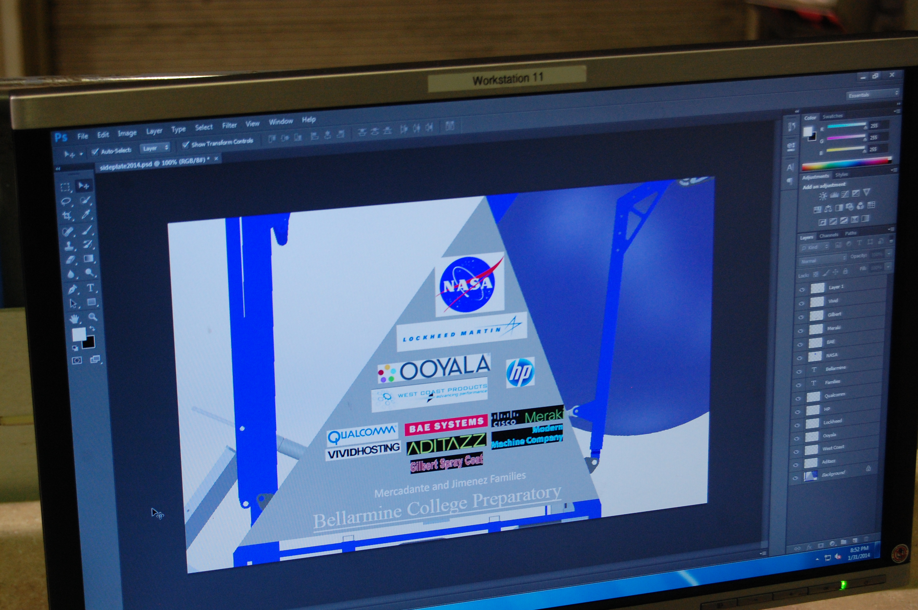
Today, several people worked on graphic design projects for our team such as this semester’s shirt, the side panels for the robot, and the “Silicon Valley Invasion” T\-shirt for Waterloo \(in the spirit of 148 and 118’s “Texas Invasion”T\-shirt at last year’s Silicon Valley Regional\). A student also searched for good fonts for “The Cheesy Poofs.”
Action Items
- Check Trello
- Help Gregorio Magarelli to put together the “Silicon Valley Invasion” shirt on Illustrator
- Help Mani and EJ wire the drivebases tomorrow
- Happy Chinese New Year!
Day 25: Waiting
By Dan Ngo ’17 and Eric Wang ’17
Disclaimer
The WiFi was down in the lab, and the shipment of anodized parts was delayed until tomorrow \(1/29\). As a result, not much work was done.
Programming
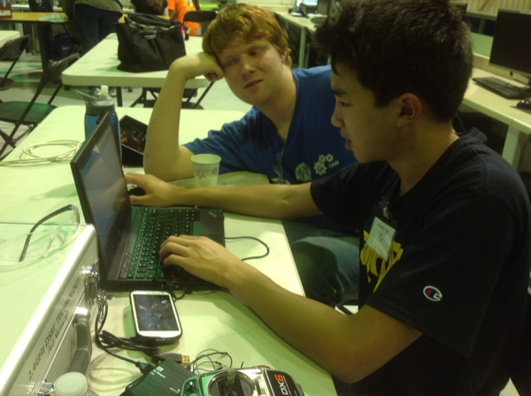
Today, the programmers tested a new \(Maxbotix MB1010\) ultrasonic sensor on the robot. This sensor will be used to determine distance to the player station wall in autonomous mode. The sensor was determined to be an improvement over the Vex ultrasonic sensor and two more were ordered. The programmers also continued programming Shockwave’s firing system.
Machining
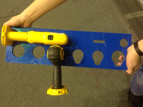
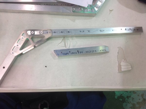
Also, members riveted the angled 1/8″ brackets to 1×1 tubes to begin constructing the final intake. Eventually, this part will be welded and powder coated. Additionally, students finished the first piece of the drill charger holder, and two more will be machined tomorrow.
Media
Students brainstormed ideas for the robot release video. If anyone wants to help, please ask Maxwell Yun.
Chairman’s Award Submission
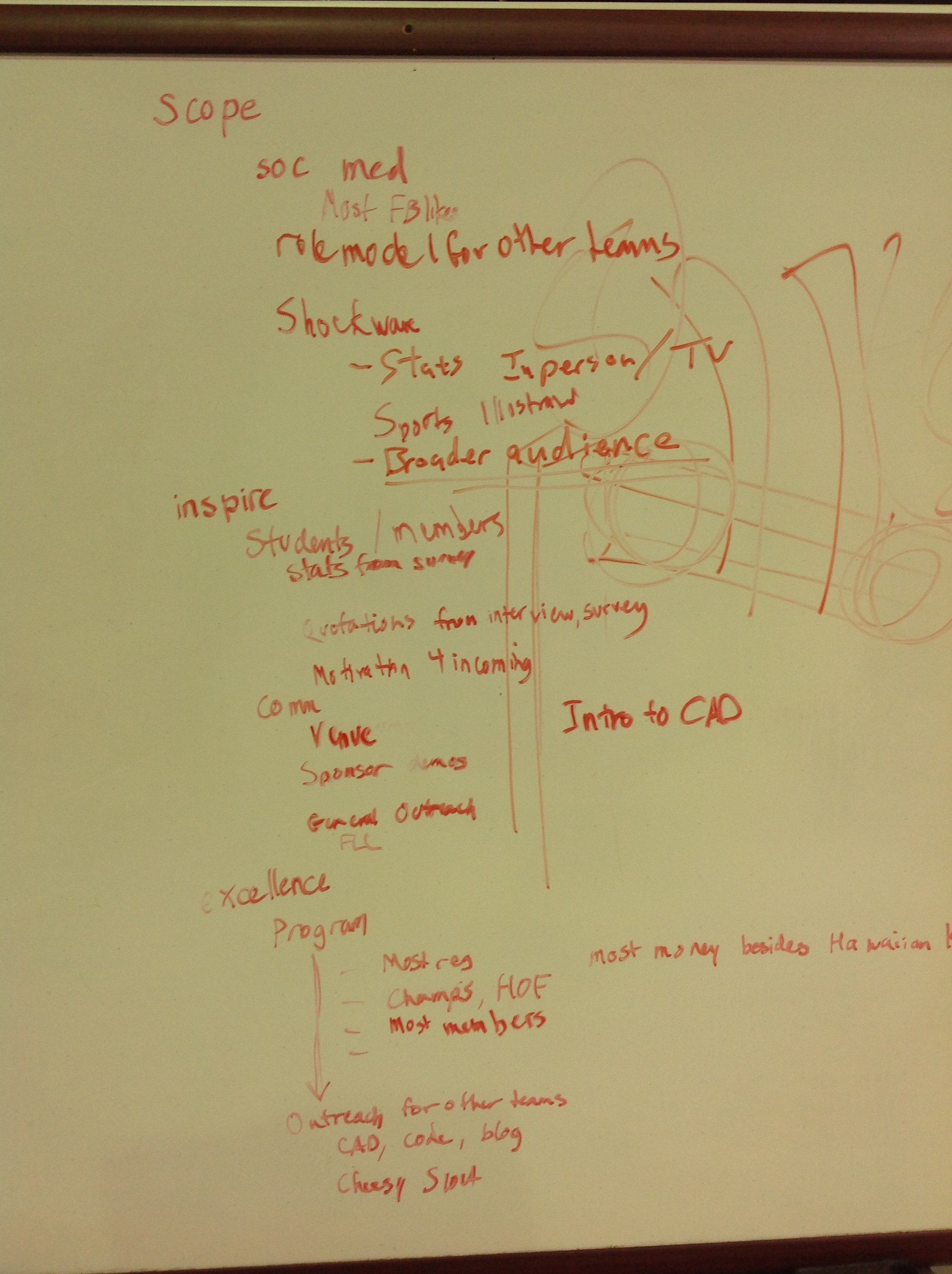
Jeremy led a few students with the Chairman’s Award outline offline, and plan to finalize writing by the end of the week.
Action Items
- Continue brainstorming and developing video ideas with Maxwell
- Keep machining and assembling parts for back intake and superstructure
- See Trello
Day 24 – Rest Day
Today was our third day of not meeting at the lab. Instead, here’s a couple snapshots of the last week at the lab.
First, here’s a video of Travis flying his hexacopter in the lab. This thing will come in handy when it comes time to make a robot reveal video.
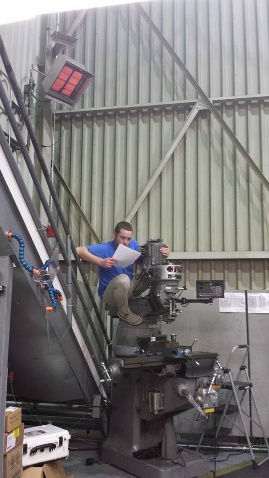
And here’s an image of Mentor Colin using the mill as a jungle gym while trying to repair it.
Day 23: Manufacturing, Ordering, Goal Construction, Lab stuff, CAD
By Clay Rosenthal
Manufacturing:
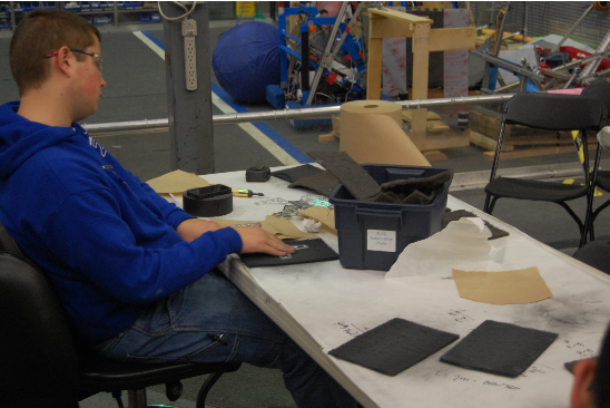
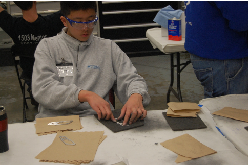
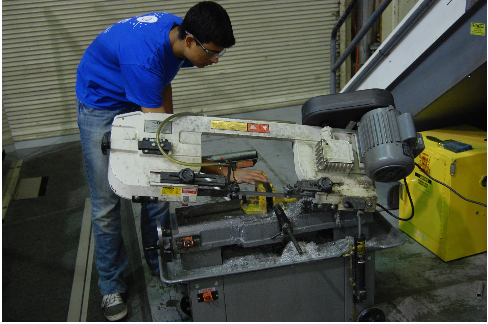
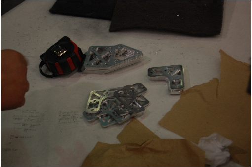
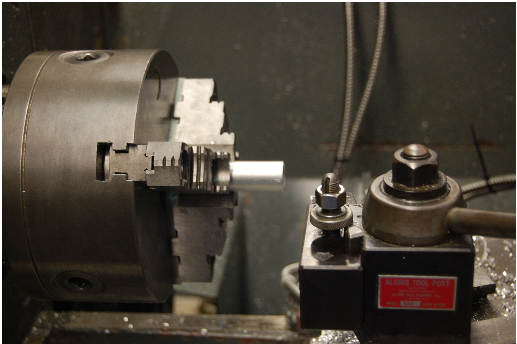
Lots of parts were manufactured today. The gussets for the superstructure were machined on the CNC and scotch brited by hand. Axle plugs were turned on the lathe. Pieces to be CNC milled later for the intake and the hood were cut on the horizontal band saw. Axles for the rollers were cut on the horizontal band saw as well. We also began programming the CNC to make the plugs that hold the superstructure subassemblies together.
Lab Maintenence
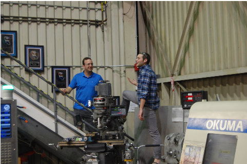
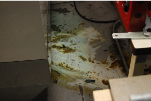
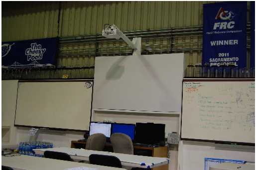
The manual mill’s starting motor is burnt out so it won’t work for now. Repairs were made throughout the day but it still doesn’t work. New parts need to be ordered for it. The CNC mill was leaking coolant today for an unknown reason. It will be looked into later in the week and fixed. The projector upstairs was mounted above the screen so it is no longer on the table.
Ordering:
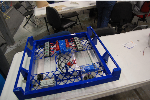
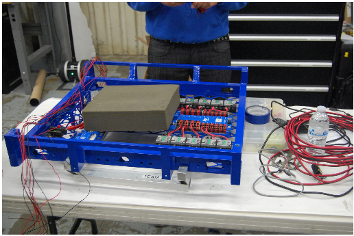
Today we ordered many parts. Specifically we ordered the wiring supplies and the electronics to **finish the robot drive by Friday.**
Field Construction
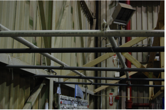
The wood covering the driver station finally broke after the repeated impact of balls landing in the goal. Modeled after the official field, PVC pipes were laid across other pipes to provide the same protection with less material. The PVC was attached to the goal and the I\-beam on the front wall of the lab. The zip ties may be replaced by something more sturdy.
Action Items
- Check trello
- When the electronics arrive, wire robot. Ask Mani or Torrance.
- CAD needs to be worked on and finalized, ask Mani or EJ.
- Manufacture more parts for robot.
- Make gearboxes to have the robot base drive by Friday.
Day 22: Trussing and Wiring
Trussing
Several students worked on building the trussing for the field. They started with 1.5 x 1.5 inch wood struts and spent all day constructing the various portions of the truss. They are on track to complete the main trussing framework tomorrow.
Wiring
A couple of students began working on wiring the robot. Specifically they worked on wiring the Talon speed controllers to the Power Distribution Board \(PDB\). They cut, crimped and soldered wires and have completed most of the wiring for the speed controllers
Clapper Popper
The “Clapper Popper” is the prototype indexer for the ball. It uses a scissor lift mechanism to push the ball up into the flywheel in order to shoot. Students retrofitted the old popper with four pistons instead of two. This helped improve the stability by evenly distributing the force of the pistons across each side. This led to less skew when the pistons were fully extended.
Brogramming
The brogrammers worked on the following:
- Getting the drive controller to turn arcs
- Add heading and scaling to the trajectory
- Fix the distance controller
- Fixing bugs and cleaning up the Drive Controller
- Adding the Hold Position Controller
- Finalizing the Data Logger
Design
We are continuing detailed design on the robot. For example, today we worked to finalizing the superstructure in addition to working on the front intake. We created part drawings for the front intake so machining can begin on these parts. Furthermore, we worked on cleaning up the rough edges of the CAD model and inserting details such as holes and other parts.
Graphic Design
The Media team worked on designing new t shirts, hats, sweatshirts, phone cases, and sunglasses for this next year.
Students came up with 3 early drafts incorporating the elements of Aerial Assist into the design elements. The phone case design is completed and students are continuing work on both the t shirt and the sweatshirt tomorrow
Day 21: Powdercoat, Programming, and Drive base Progress
by James “Mikey” Carroll ’15
Prototyping
Today, a group of students continued to work on and improve the indexer prototype. The indexer, the mechanism used to raise balls into the flywheel shooter, features a claw-like design that lifts the ball as the two arms segments of the claw come together. Furthermore, students improved upon the previous indexer design, which included one piston and two gears, by adding a second piston (one for each claw arm). The intentions of this design are to improve strength and allow each arm to move independently, thereby increasing ball stability and raising accuracy.
Manufacturing
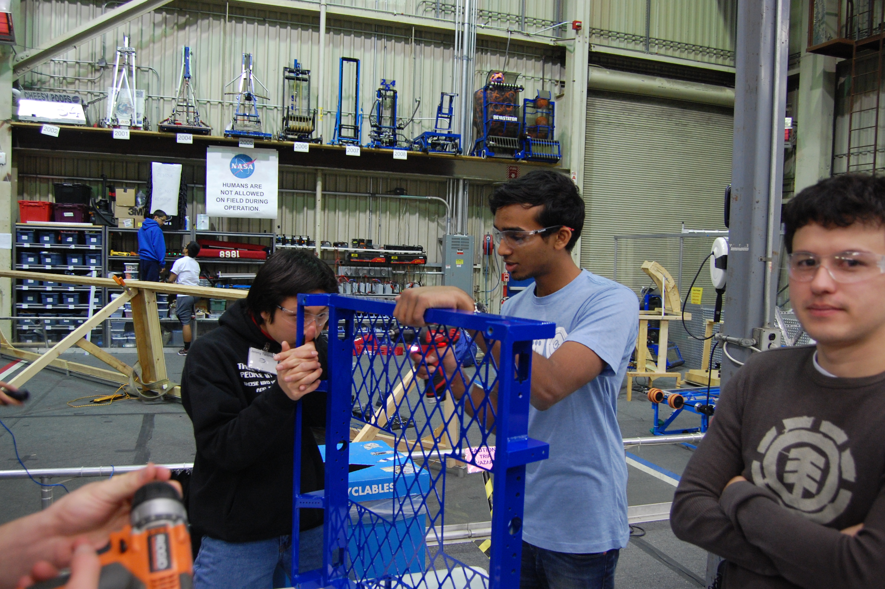
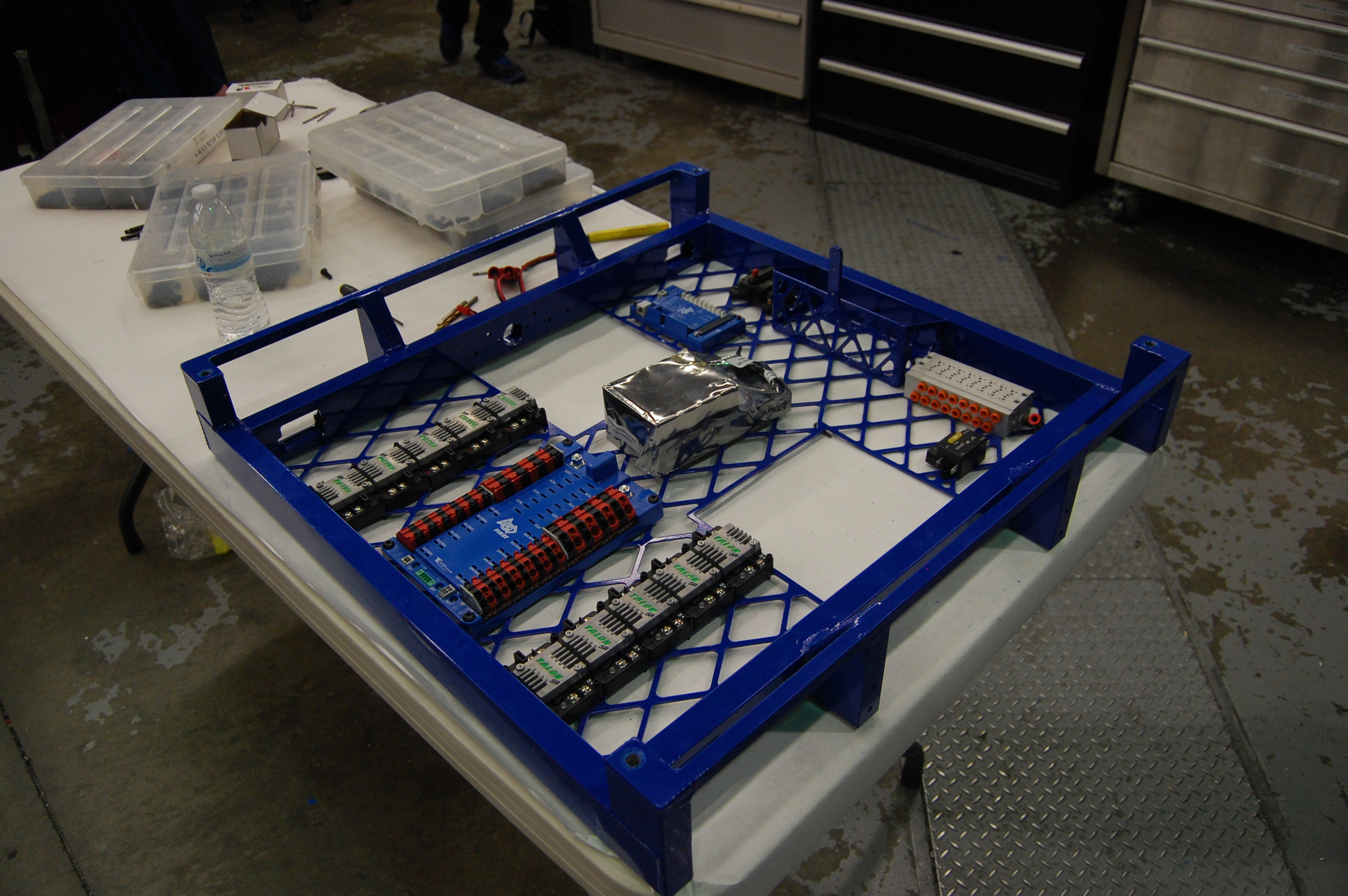
Students began to construct the drive base chassis for the finalized robot. First, students drilled and tapped holes in the chassis, then installed hardware and electronics into the base plate, in particular the main switch, the power distribution board, the digital sidecar, and the Talon motor controllers. Students are beginning wiring.
Programming
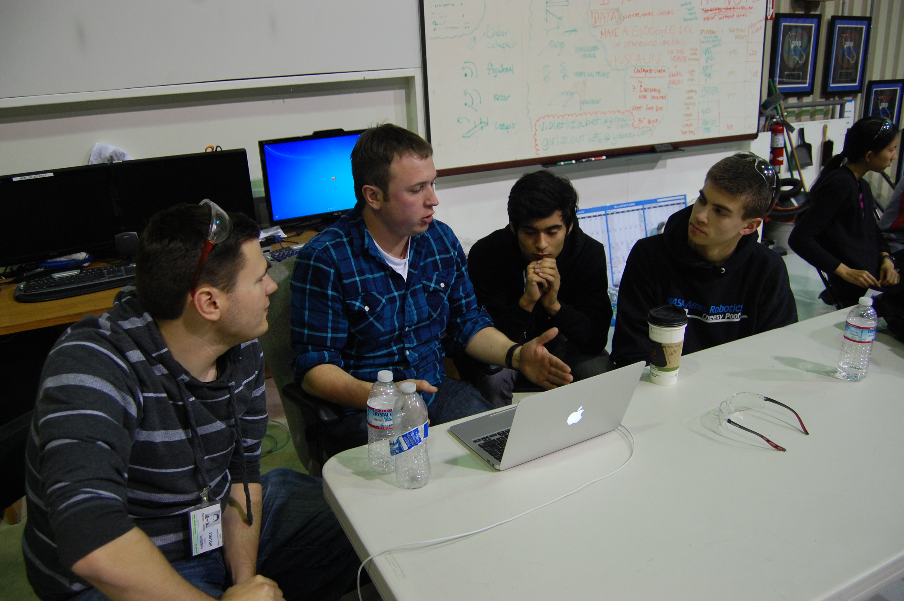
Work continued on designing and fine tuning the code for the robot data logger. This log includes information directly from the robot’s sensors, such as drive speed or intake speed. The log also provides easy visualization of all movements of the robot and quickly reveals issues with the robot, such as one motor running faster than another, in real time. Students will also use the information from this program to tune PID.
Field Construction
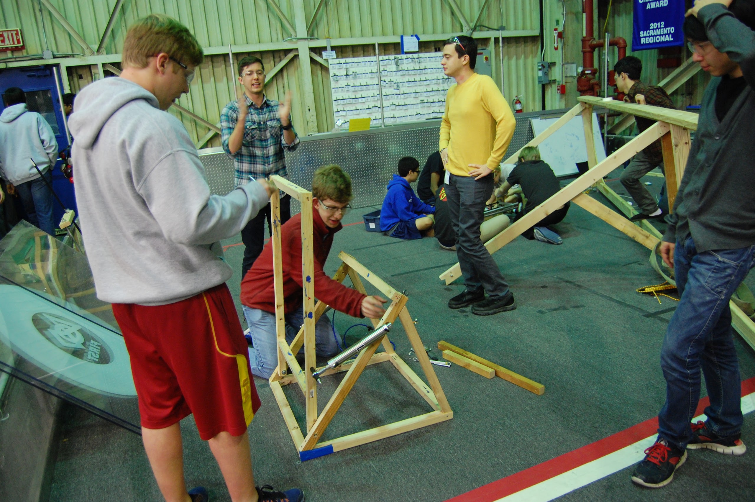
Work continued on the construction of the truss for the field. Students completed a CAD design for the truss.
Chairman’s Award Submission
Students resumed work on Team 254’s Chairman’s Award submission, making lots of progress on the executive summary portion and the essay portion of the entry. Work continued toward a finalized thesis for the essay portion
Action Items
- Add 4 gauge wire to both robots (Contact Mani Gnanavisam if interested)
- Connect Talon motors to PDB and digital side car (Contact Mani Gnanavisam if interested)
- Finish construction of the truss (Contact Mani Gnanavisam if interested)
- Put a backing on the shelf (Contact Mani Gnanavisam if interested)
- Check the Trello (Contact Abhi Kumar if interested)
Day 19: Advancing Prototypes, Prepping for Welding
by Joncarlo Avila and Brandon Wui
Prototyping
Today, we worked on prototyping an improved catcher and ball indexer. Our new catcher consists of 2 pistons that open and close the catching mechanism. We also removed the intake and shooter from the Overkill practice drivetrain for easier testing.
We made two new indexer prototypes with the goal of minimizing piston use to save air and weight. One group built a prototype that used a 6″ stroke piston to simply push the ball into the flywheels. Another group finished another variant of an indexer. This one features a 3″ stroke piston that pushes a linkage together so that it “claps” to move the ball up. The clapping indexer worked slightly better than the linear one and also uses a smaller piston. Late at night both of these prototypes were tested with the shooter and both showed consistent shots and improved accuracy over the former indexer.
Programming
Machining: Drive base
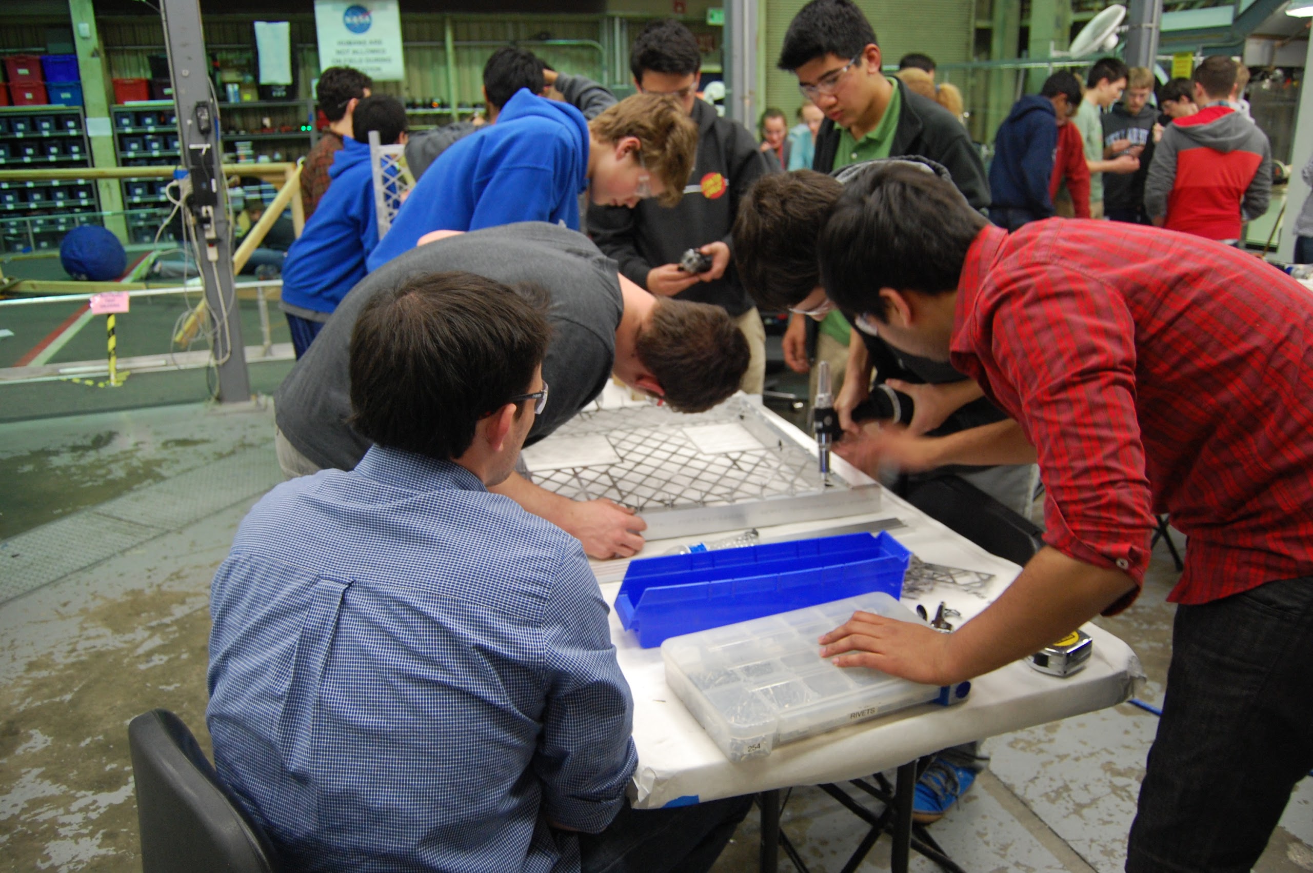
Today, we received our waterjet base plates from sponsor BAE Systems. We riveted the plates to the chassis rails which were machined over the weekend and jigged the weldment for welding. Students also worked with wire brushes to clean the aluminum oxide off of the parts to help with welding prep. The drive base is now ready to be sent out to be welded by sponsor Applied Welding Technology and will hopefully be received tomorrow so that we can prep it for power coating.
Action Items
Check the Trello!
If drive base is back from welding, prep it for powder coating.
Continue working on the indexer prototypes, testing with variable ball sizes and PSI for consistency.
Day 18: Prototyping, Testing, and Programming
by Chris Powers and Jack Lee
Prototyping
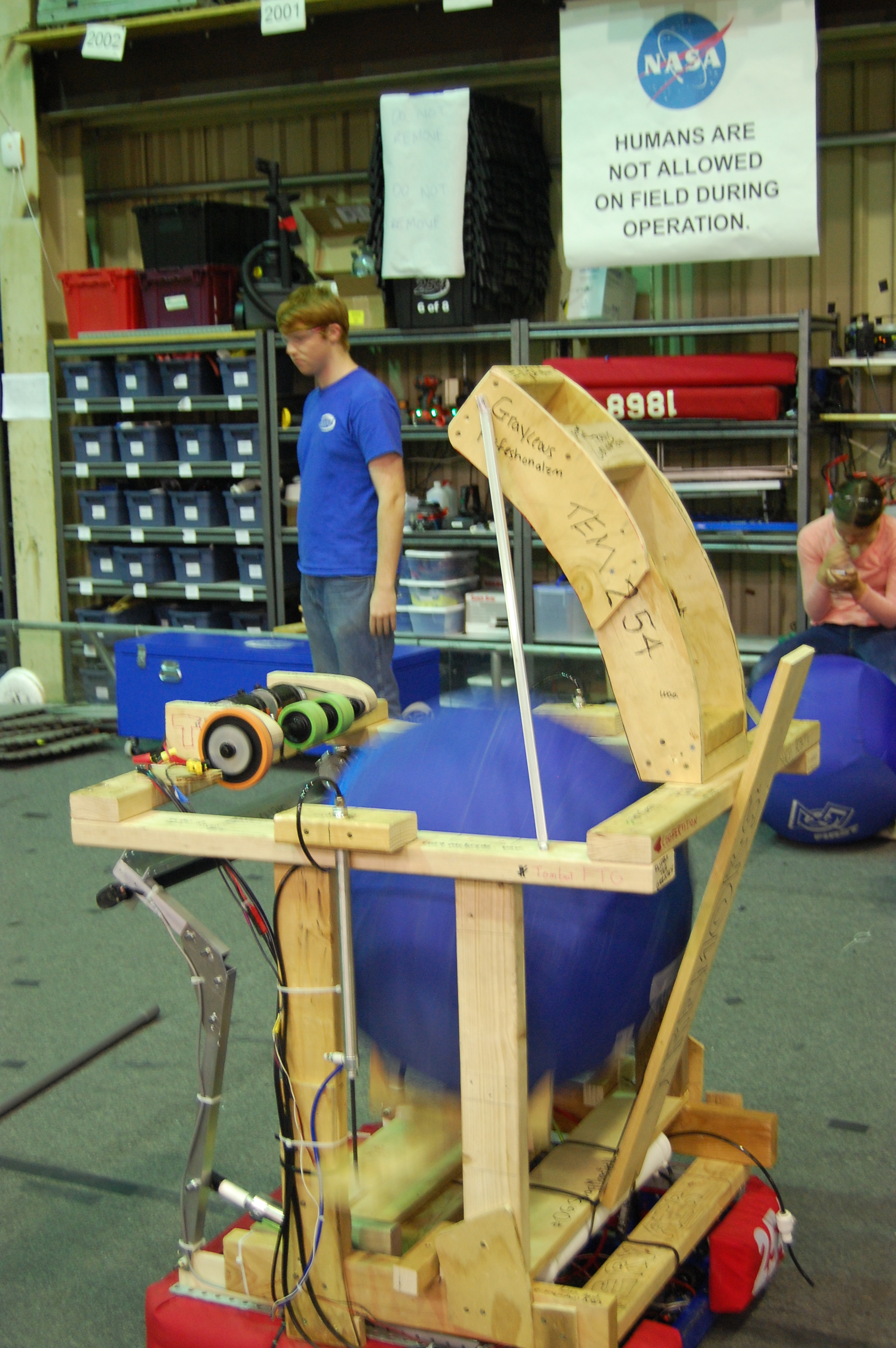
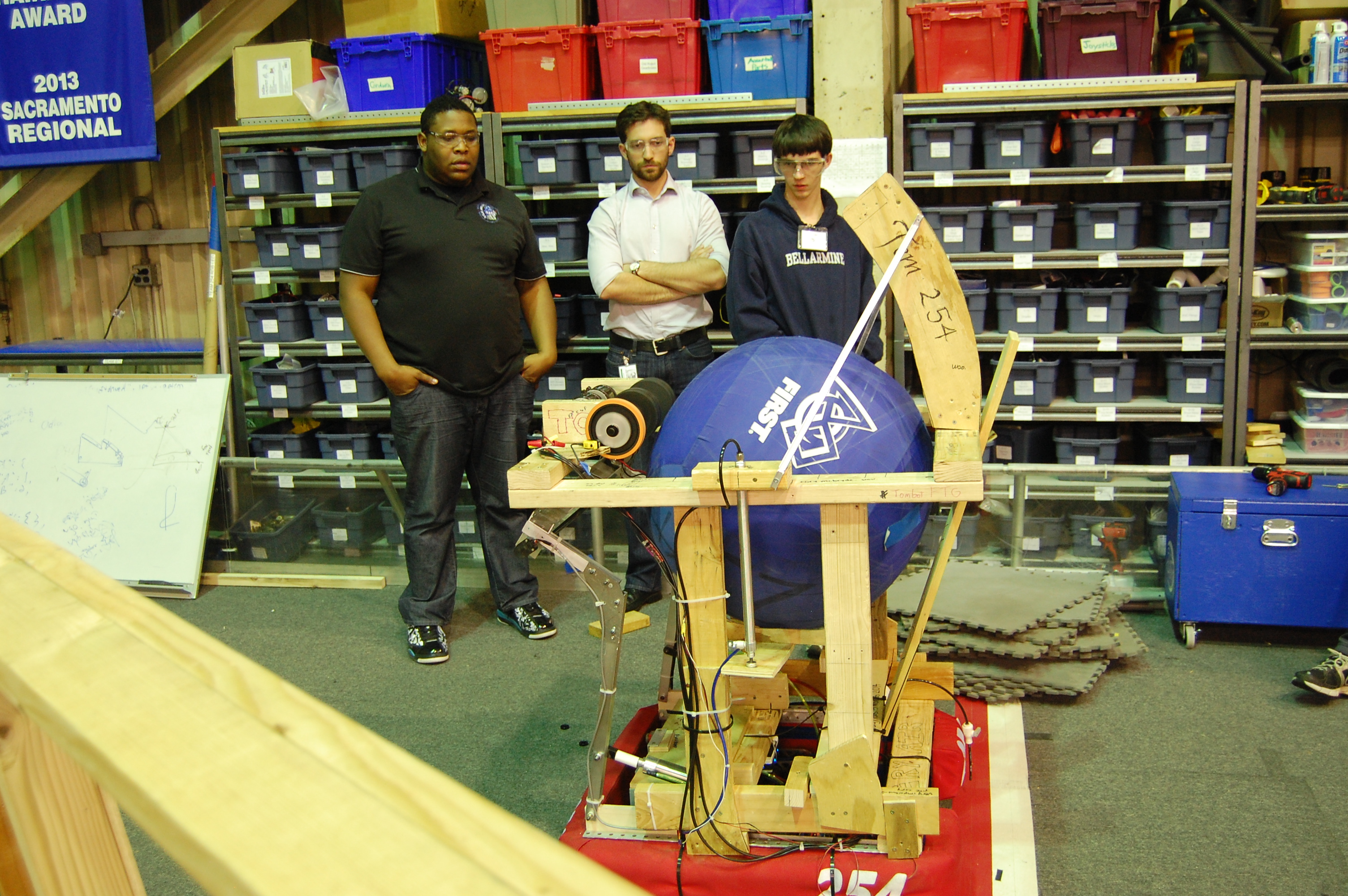
Today, work continued on testing the prototype robot’s lift mechanism, which uses pneumatic pistons to lift the ball from the intake of the robot to the flywheel shooter. This lift worked successfully during most of the tests. The hopper prototype uses a V-shaped mechanism to lift the ball.
Machining
A group of students created side plates for the gearbox. After the plates were cut and deburred, they were machined on the CNC mill. All pieces for the drive base have been manufactured except for side plates.
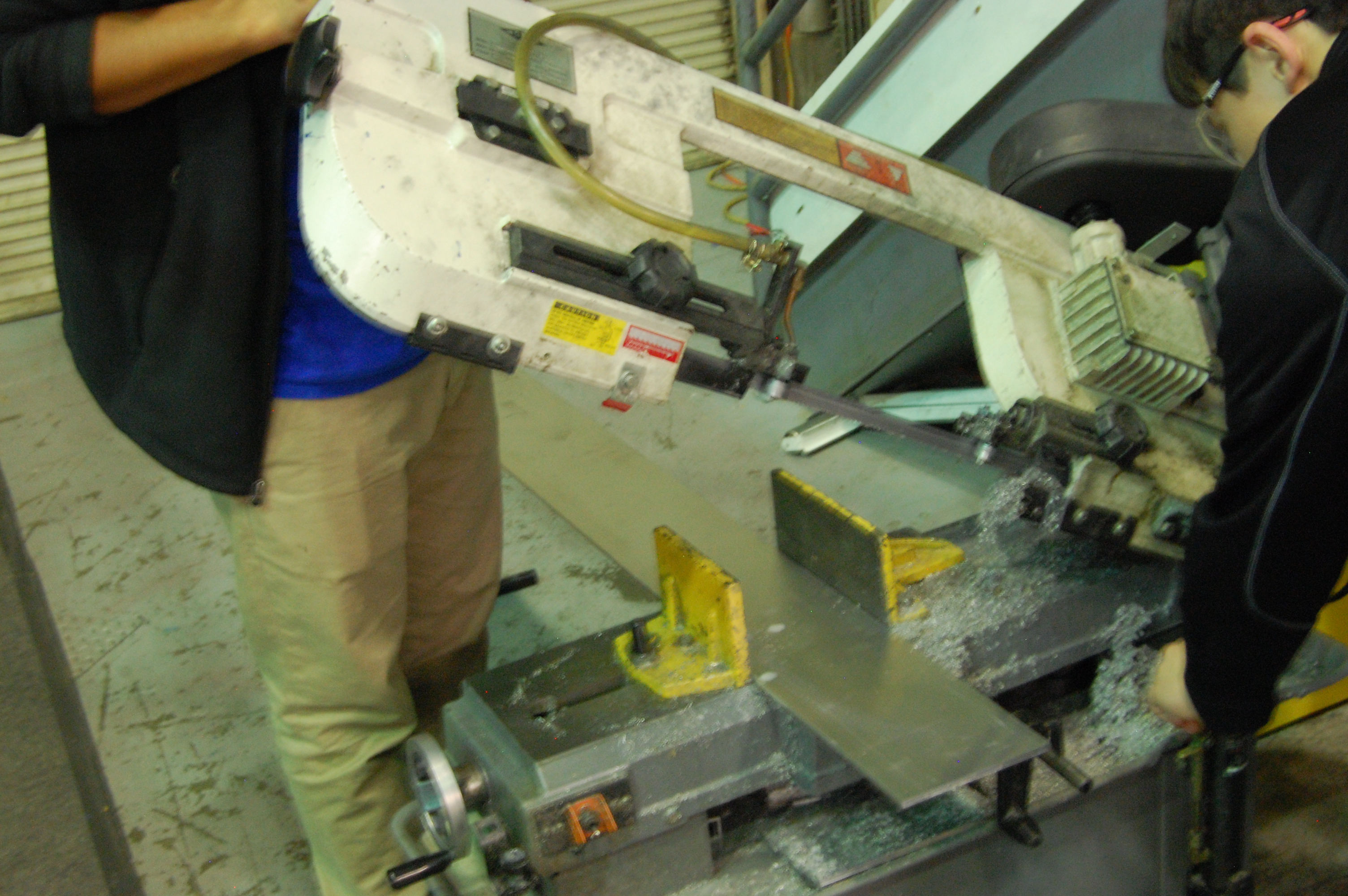
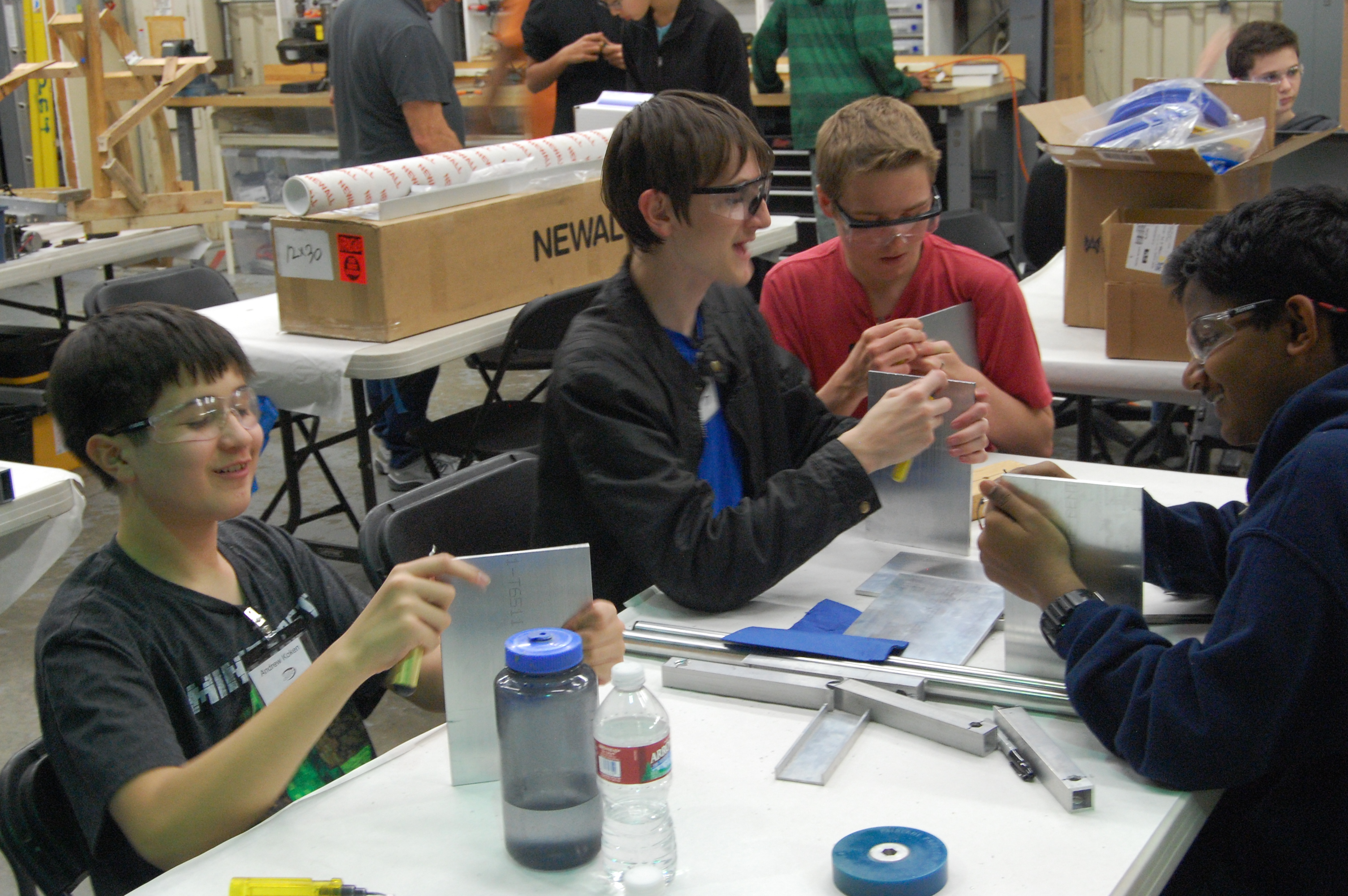
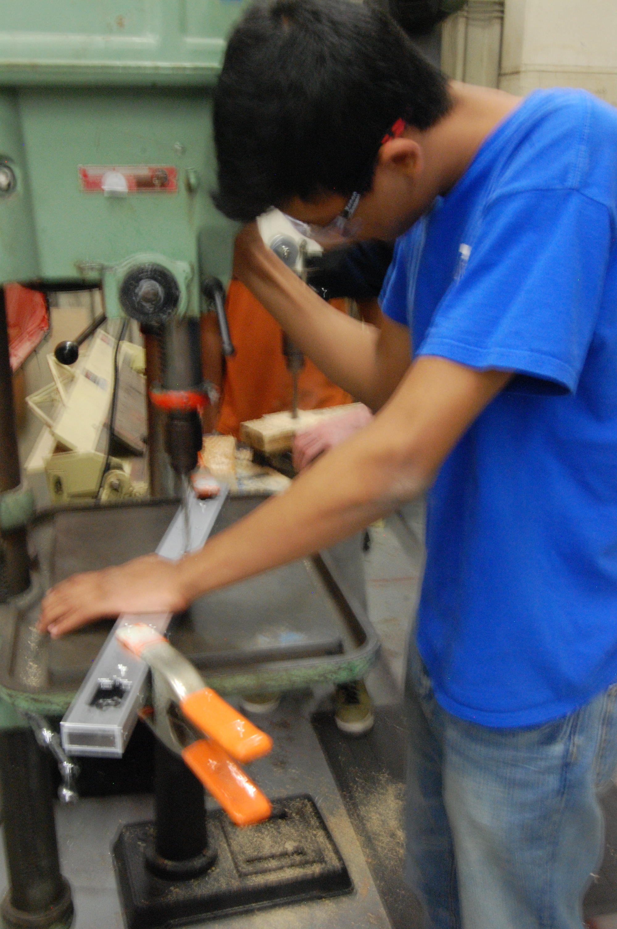
Work began on constructing a truss for the field. Also, the wooden goal was disassembled and the official goal will soon be set up.
Programming
The programmers worked to fine tune the shooter mechanism. They created a graph of the model voltage for the shooter and compared it to the actual data with equations. This will allow compensation for the variable factors that affect the input voltage, and will increase shot accuracy.
Testing
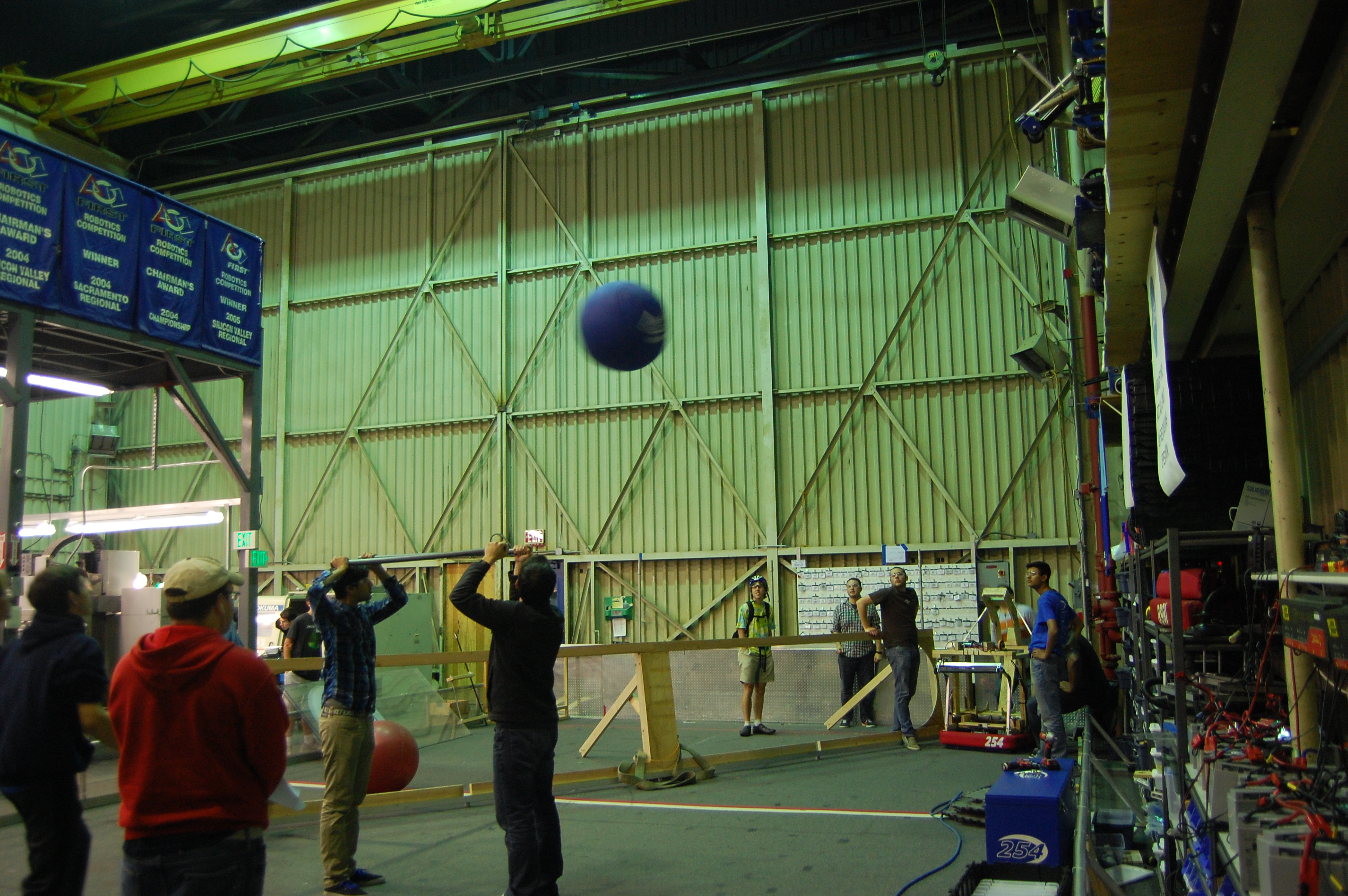
Many students contributed to testing and refining the shooter mechanism. Many different variables were adjusted to determine the best conditions for accurate and powerful shooting. The shooter speed was varied between 4000 and 5000 rpm and the wheels for the shooter were replaced with slightly larger ones to increase flywheel energy. A banner sensor was added to measure flywheel rotational speed using retroreflective tape. The new flywheels shoot 12 vertical feet, high enough to clear the truss.
CAD
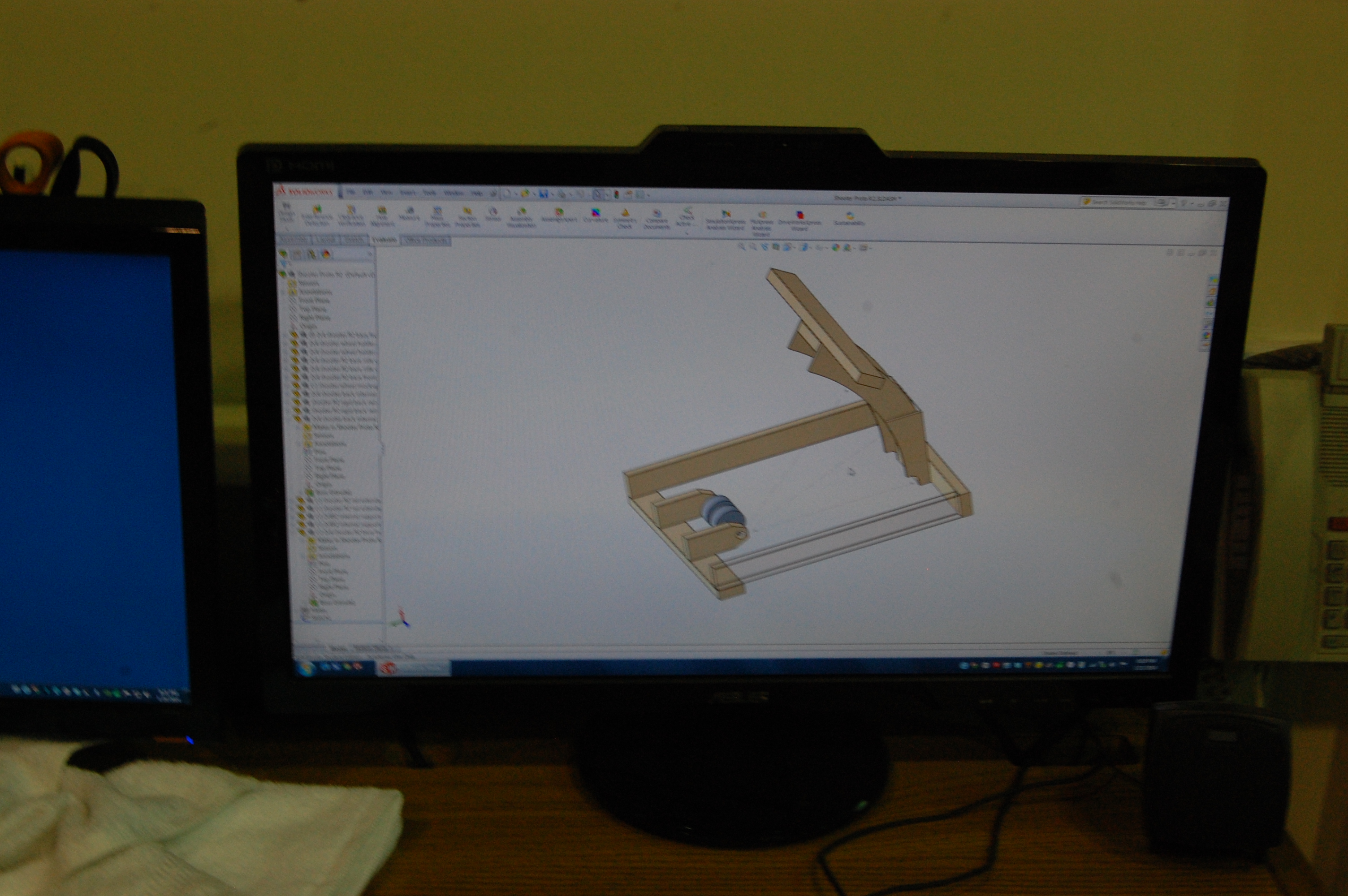
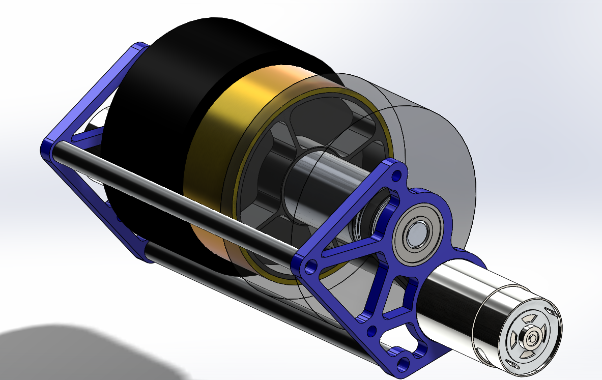
We began work on the design of a new prototype shooter. This shooter will have a sturdier hood and a lighter wheel. The hood will also have a hood extension that can be attached to replicate the two-position hood on the actual robot.
To design the shooter, students learned about moment of inertia and used SolidWorks to roughly estimate the mass and moment of inertia of the current extra weights on the shooter prototype. We used those numbers to estimate the mass and moment of inertia that we can add to the flywheel in place of the metal gears currently in place on the shooter. These numbers allowed us to model a copper tube with less mass and a similar moment of inertia which will be pressed around an aluminum hub and installed on the robot. More information on moment of inertia is available online.
Action Items
- Check the Trello
- Assemble the weldment
- Start on catcher prototype with Colin
- Test the new shooter wheel and new prototypes thoroughly with Abhi: build adjustable hood for testing shooting angles: test for shot distance for hood angles and ball pressure
- Complete CAD of bumpers, superstructure, and battery cart with Andrew and Mani
- Possibly build new flywheel weight.
Day 17: Rest Day 2
Today, there was no official meeting at the lab. However, several team members continued to work on robot design.
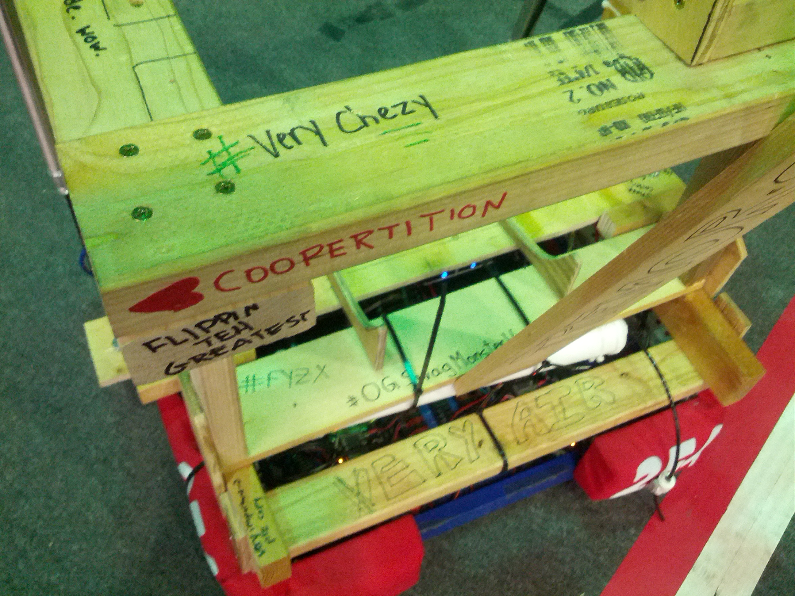
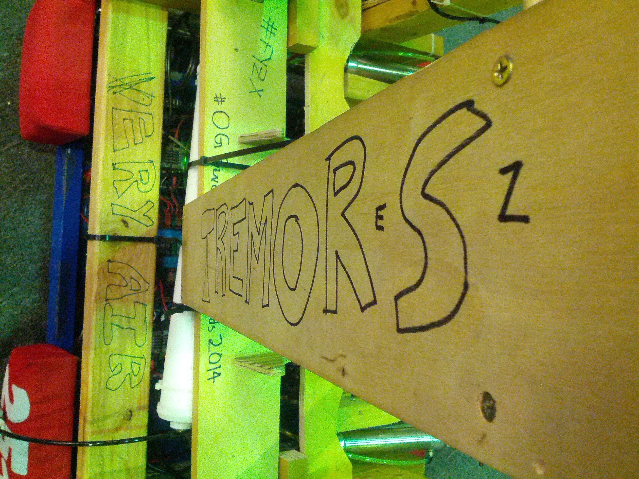
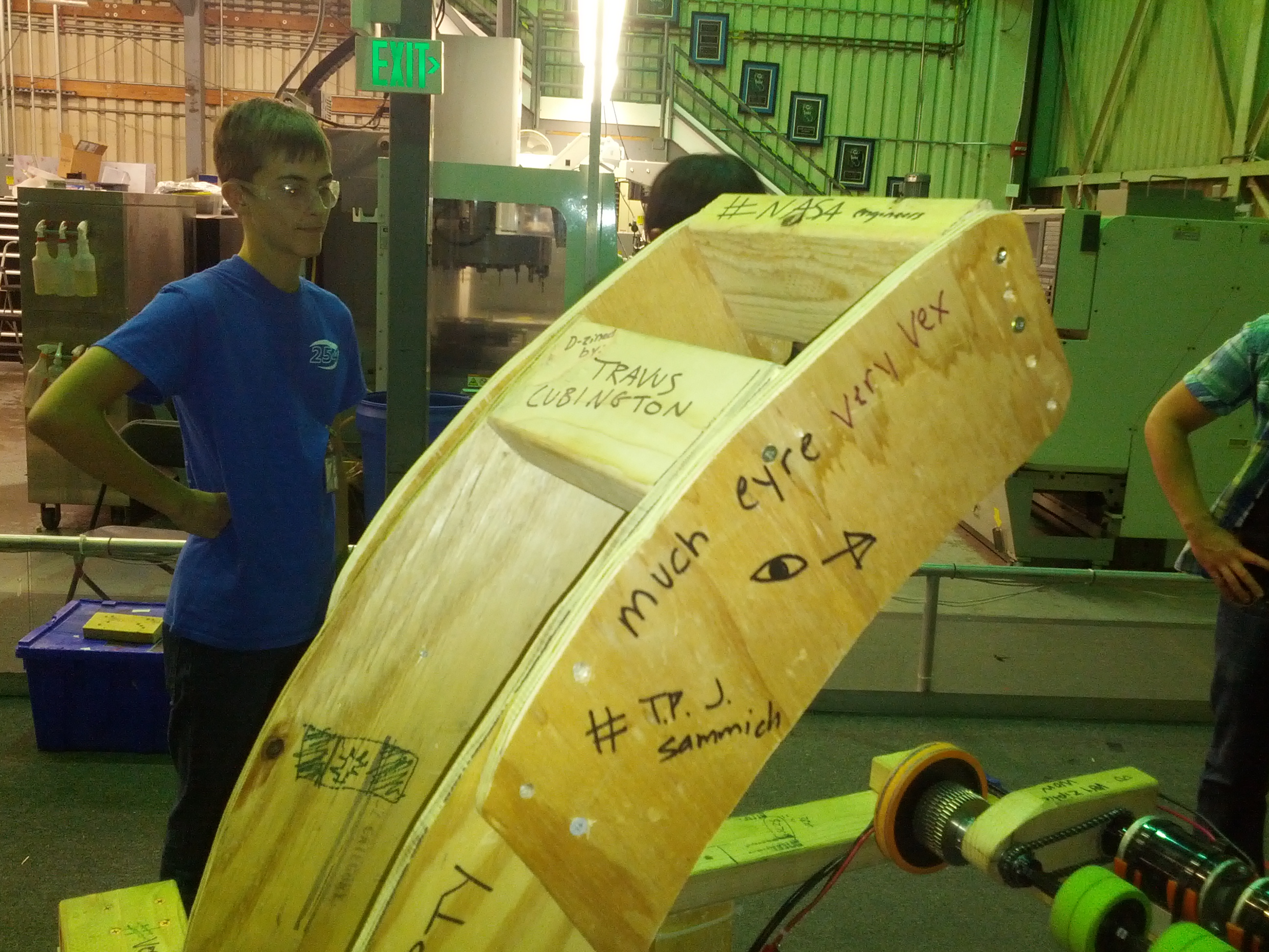
Instead of a normal blog post, have some pictures of the latest prototype (sponsored by Tem 254: Teh Chezy Pofs). As you can see, the students decorated the robot.
Day 16: Programming, and Prototypes
Programming
Today, the programmers worked on two major projects and a smaller one. The two larger projects were a data logger for the robot and an app for members to check their FRC Hours. The smaller project was to get Adobe products which had been generously donated to the team onto a few of the lab computers.
The Data Logger will return data from all the parts of the robot and plot them on a graph.This will help the programmers to detect what is going on in different parts of the robot and at what time it happened. They plan to fix the single plot graph and make the logger capable of tracking different sub-systems.
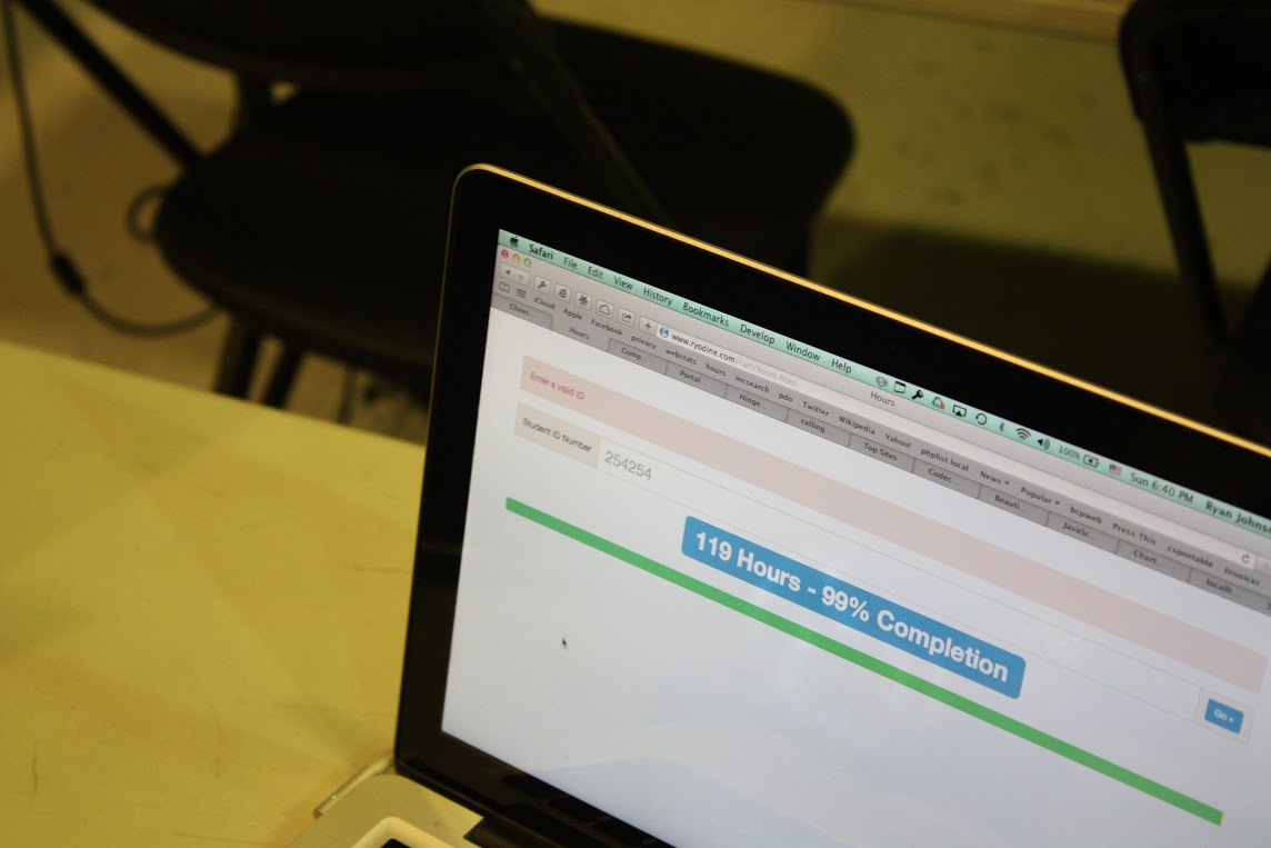
The FRC Hours mobile app makes viewing member hours more accessible. This should make it easier for members to track how many hours they have completed and how many more they need to do. The programmers plan on adding more functions onto it later, including even a signup system for the builds.
The final thing that the programmers worked on was putting Adobe InDesign, Photoshop, and Illustrator onto the lab computers. This took a lot of time as there was one CD of each to go around, and ultimately, they could not finish installing each by the end of build.
Pit Shelving Box and Robot Shipping Crate
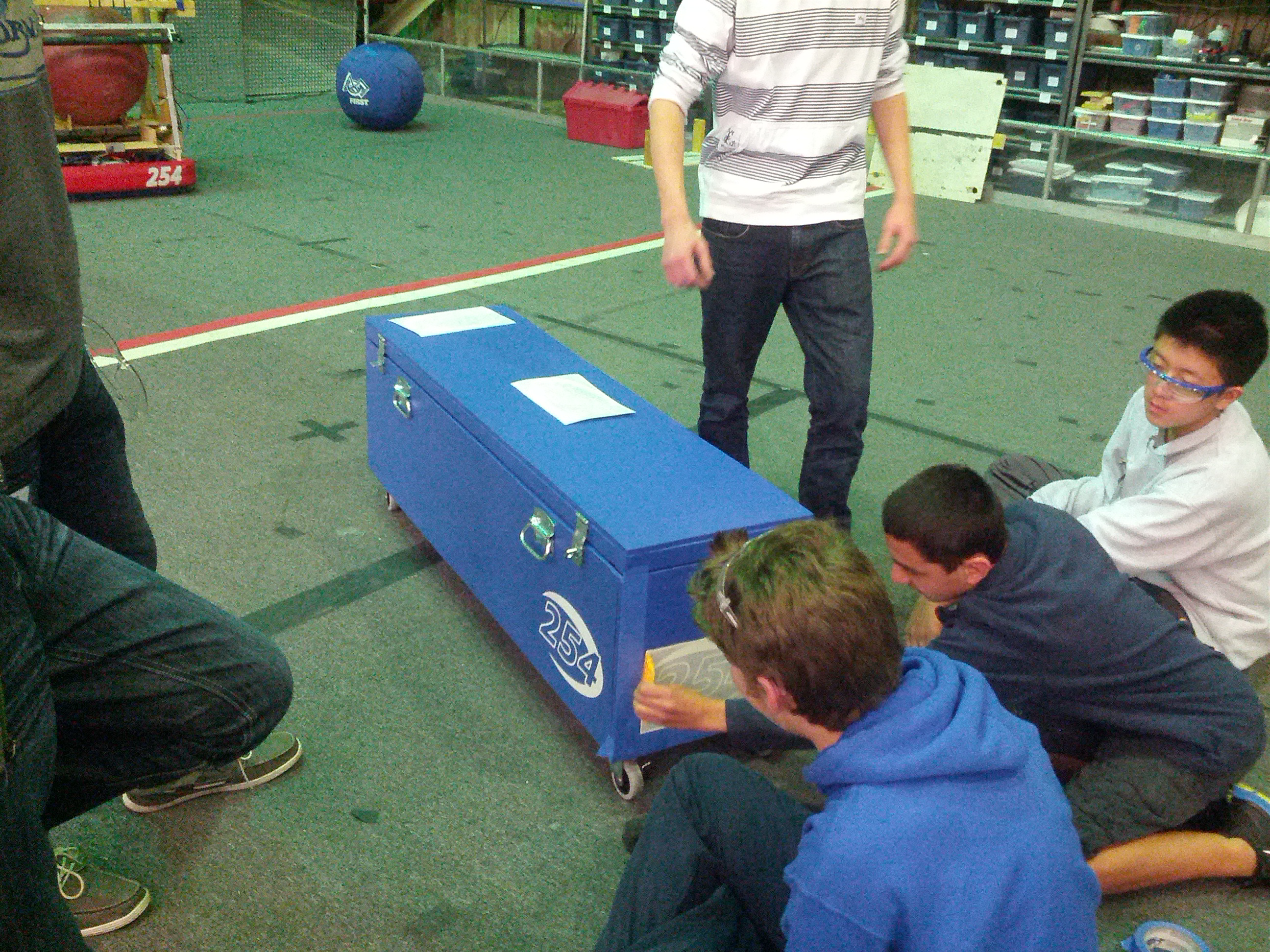
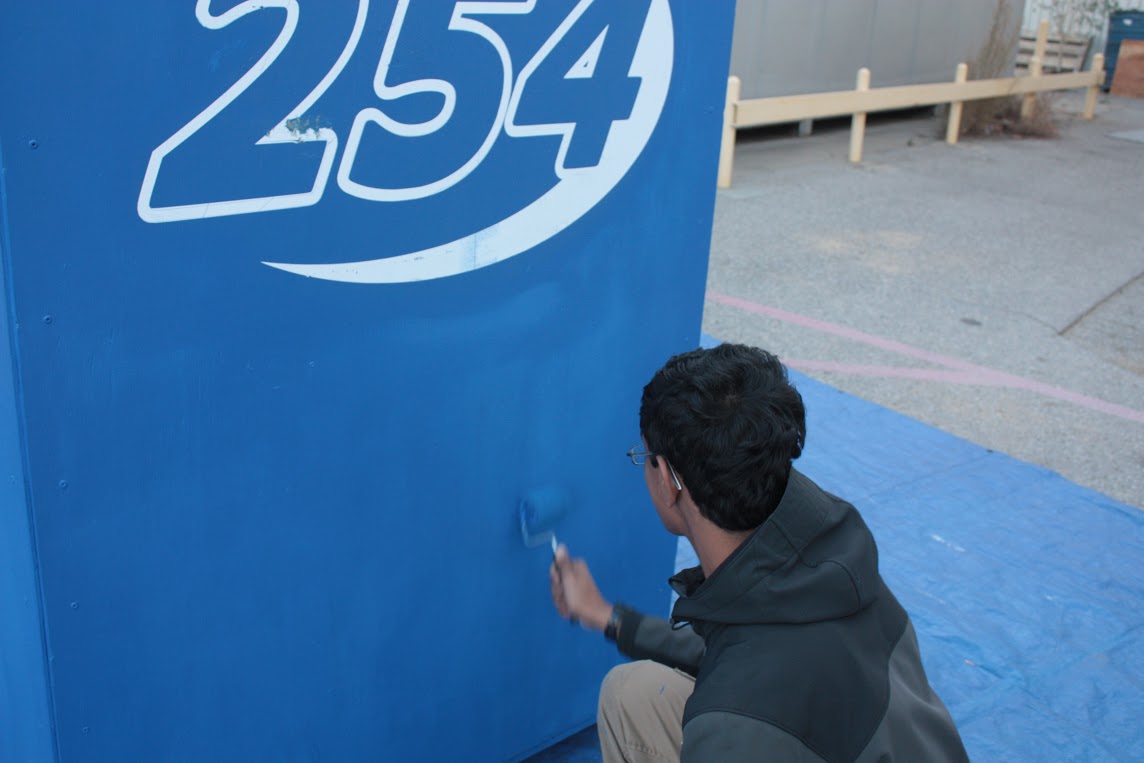
Today, we also upgraded the pit shelving box. The base was re-painted in two coats, a flat coat and then a secondary semi-gloss coat, all in blue. The cover of the box was also redone, using less pieces so that it looked cleaner. Two handles and four wheels were added to enhance box mobility. The hinges were also supplemented with gas springs to hold the lid open during loading and unloading.
Members also touched up the paint on the shipping crate, last painted in 2011. The two new boxes look great and we’re excited to bring them to competition!
Prototype Catcher
Students built an improved catcher that more closely resembles the CAD (one that can actually fit on the robot). They attached pistons to the catcher so it could open and close. They also brainstormed the structure of the side of the catcher. They were unable to finish the rest of it due to a lack of material, which will all arrive by the next build. They will then attach the material to the side and the back of the catcher so that the ball will not fall out of the catcher upon being caught. Additionally, they added some blue paint to the structure of the robot prototype.
Manufacturing: Bumper Supports
Students also used the mill to make the metal bumper support brackets, which are needed to attach the bumper to the robot drive base. They were able to finish this and will soon be riveted together and sent out to be welded.
Action Items
- Sign up with Kevin Vincent, Greg Magarelli, and Peter Feghali if you are interested in helping or have the skills to contribute to the media team (in short, if you want to be a part of any or all of the following: photoshop, graphic design, photography, video design and editing, 3-D animation, website operation, social media updates, publicity releases, and CAD rendering)
- Help Stephen and Brandon install Adobe software on the lab computers
- Brainstorm additional functions for the 254 Hours Mobile App for Brandon and Stephen
- Brainstorm ideas with Ian Kirkland for media posts
- Machine the front brace, back brace, and top plate for the cordless drill holder.
Day 15: CAD, Machining, Prototype Robot, Programming, S’MORES!
by Clay Rosenthal
Important Reminder
Wear safety glasses on bottom floor of lab at all times! Even if you are not machining or there are few people in the lab this is a requirement.
CAD
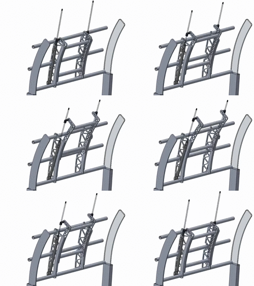
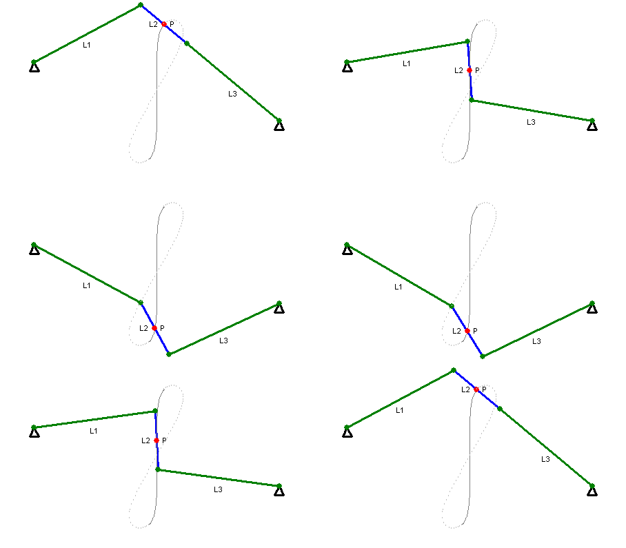
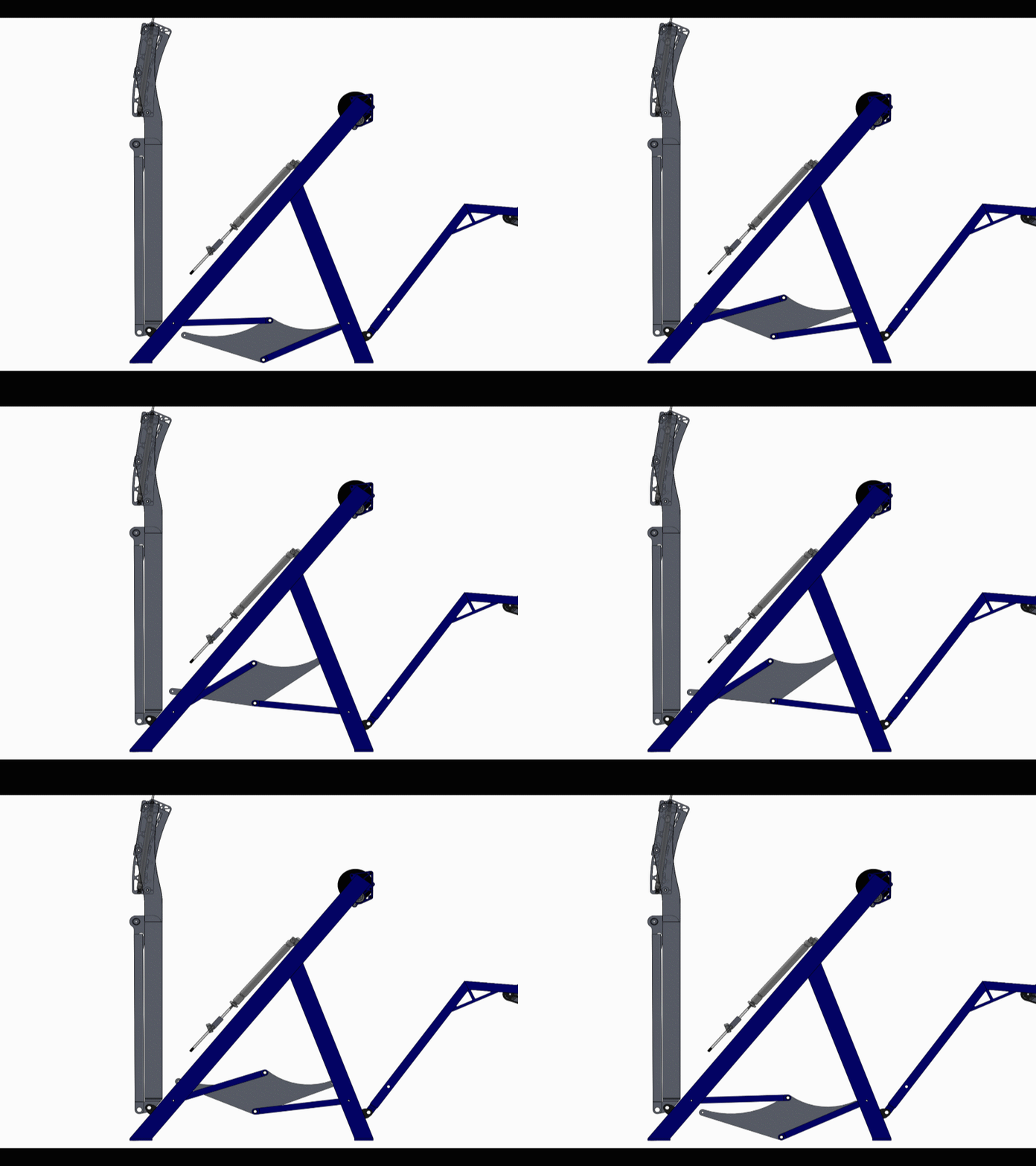
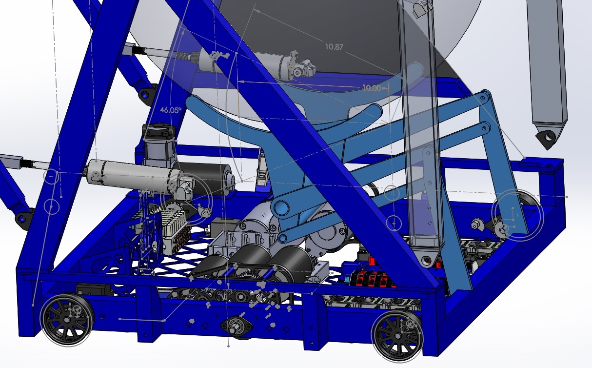
Today, work continued on the design of the inner plates of the hood. We also investigated the use of a Watt’s linkage for lifting the ball into the shooter. The Watt’s linkage has a large (approximately) linear region in the center of its travel that we could use to lift the ball straight into the shooter. A separate lifter idea used a 4 bar linkage to lift the robot. Work on both of these projects will continue tomorrow.
On the drill holder, holes for the large Milwaukee and DeWalt drills were prototyped today and the CAD was approved. This will soon be sent to Good Plastics for routing.
Buttons were added to the CAD of the control board to our operator’s specifications.
Machining
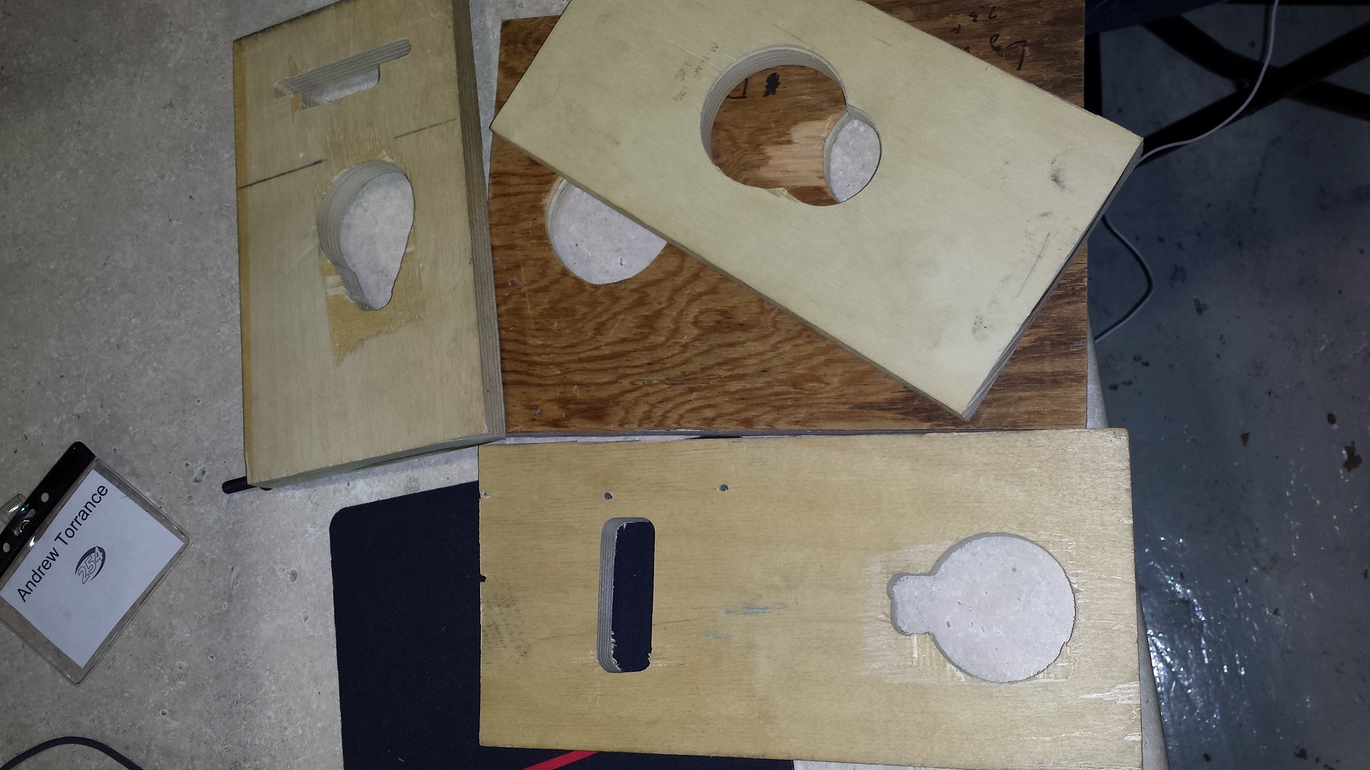
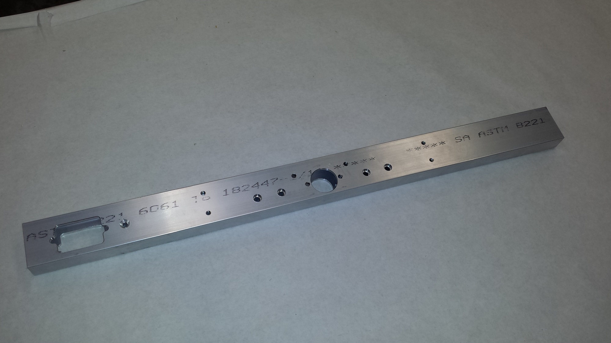
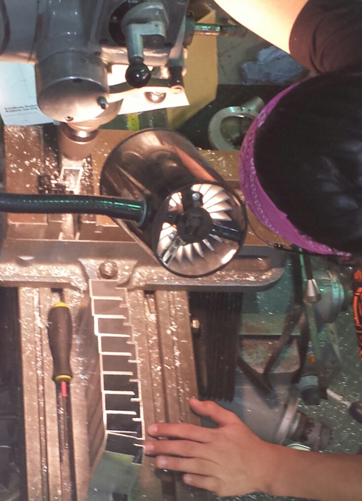
More pieces for the drivebase chassis were cut today including 4 frame side rails. Also, middle bumper supports were machined with the mill. These will eventually be riveted together with the rest of the chassis and sent out to welded and powder-coated.
Robot Prototype
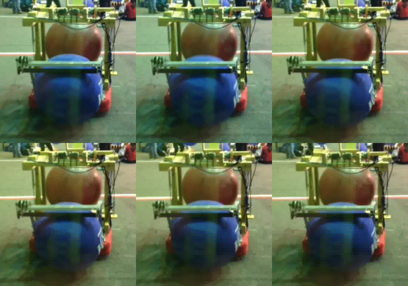
The prototype was tested today. The robot was able to intake, “pop” the ball, and shoot it with driver control in the afternoon. The robot has balance issues that can cause it to tip and fall on occasion, as shown in yesterday’s post. In the evening adjustments were made and there arose complications involving the pistons for the popper not rising at the same time. This was fixed but will need to be perfected. The hood was extended to change the firing angle and the fly wheel had an extra wheel added. A button was added to the intake to help with autonomous. Also a more solid back plate was added to help keep the ball in. All of these modifications are making the shots faster and improving consistency and accuracy.
Programming
Today, the programmers first worked on designing an auto-intaking control loop to hold a ball in the intake off the ground while another ball is in the robot. This will allow the robot to transport multiple balls in autonomous. The control loop started very rough, simply running the intake whenever the ball lost contact with a bumper switch. Later, we added an encoder to the roller and designed a control loop to smooth the intake.
The second thing that we focused on today was the data grapher webpage. We decided what the layout of the JSON file that we send would be. We eventually decided to go with one big file that would contain many separate JSON objects for each graph.
Finally, the programmers worked to implement a simple two-ball autonomous routine. While it takes far longer than ten seconds to run, it is a good proof of concept.
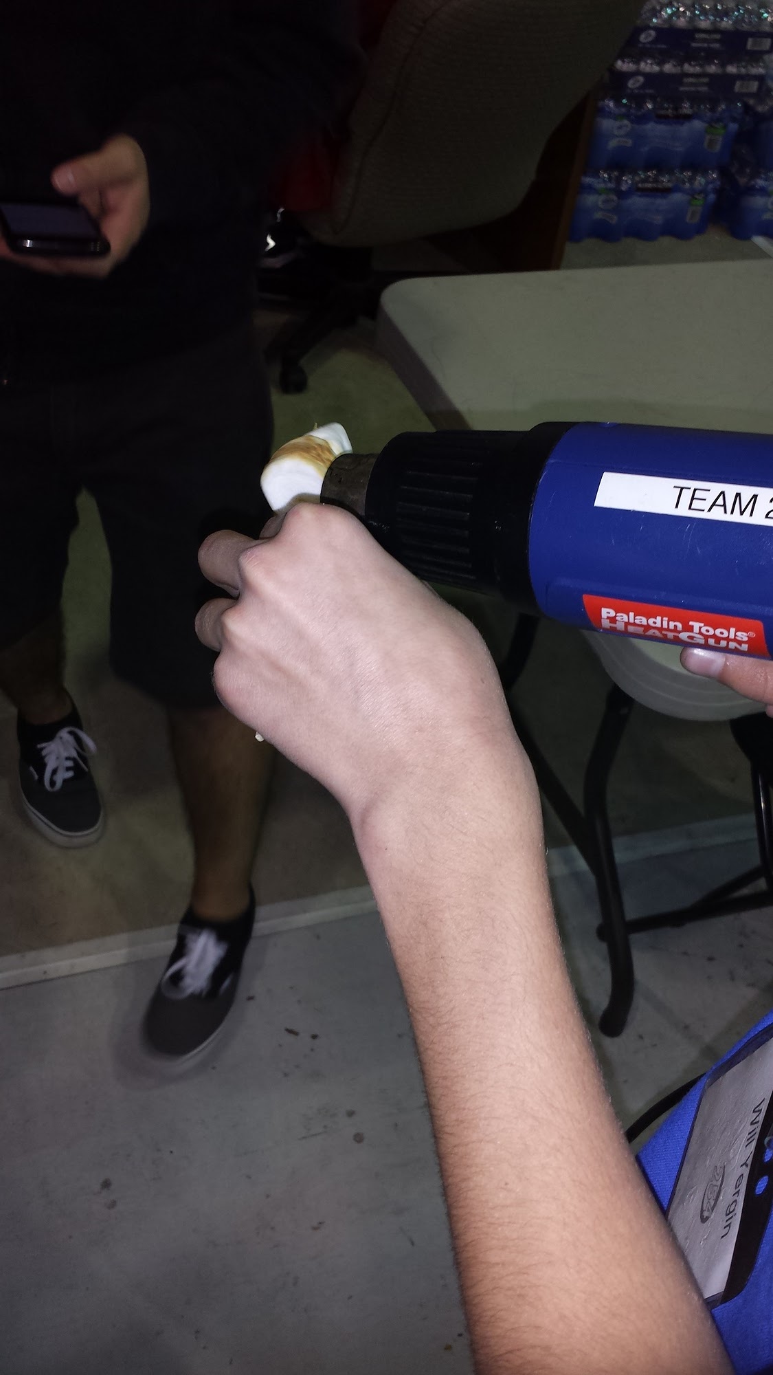
S’mores
Late at night, we made s’mores using a heat gun. It worked really well and the s’mores tasted great! We should do this more often.
Action Items
- Check the Trello!
- Finish refurbishing of the pit shelving crate (repaint, attach hinges/latches, add wheels)
- Programmers: test flywheel controller and intake state machine.
- Begin CAD of the Battery Cart.
- Continue improving robot prototype, make more consistent.
Day 14: Working Robot Prototype, CAD, Chairman’s Award Begun
by Christian Bagamaspad and Michael Simeon
Robot Prototype
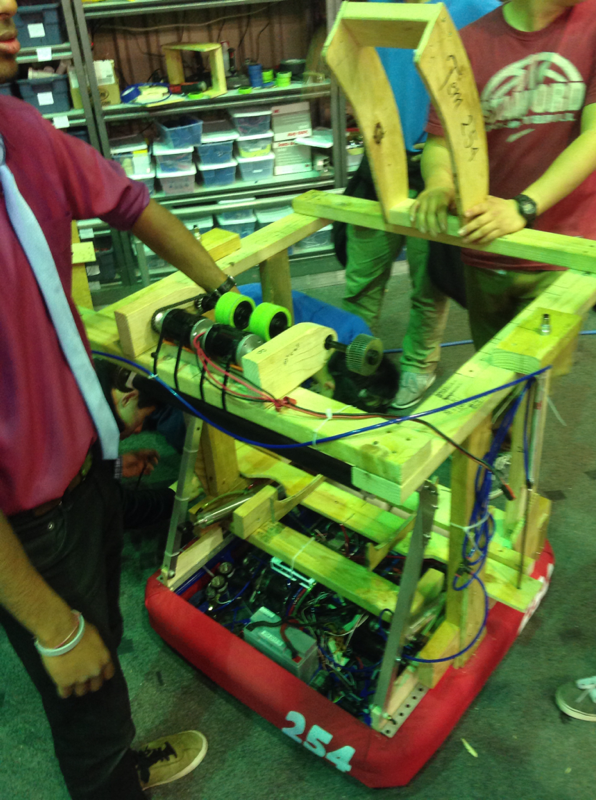
The robot prototype changed considerably today. First, the shooter prototype was mounted to the 2013 drive base. The robot can now drive, intake, load the ball, and shoot in one test. Results were very promising and tests showed the robot can pick up and hold two balls, sequentially index and shoot them into the goal. Later, shots will need to be fired more consistently, and the “popper” piston mechanism will need to be more robust to provide better shots and prevent the ball from getting jammed. This mock up prototype of the robot could possibly be used by programmers for early autonomous testing. This is one of the first times in recent years that team has built such a large compilation of other prototypes. Due to the simplicity of its design compared to previous years, this prototype will actually be somewhat similar in functionality to that of the final robot.
CAD
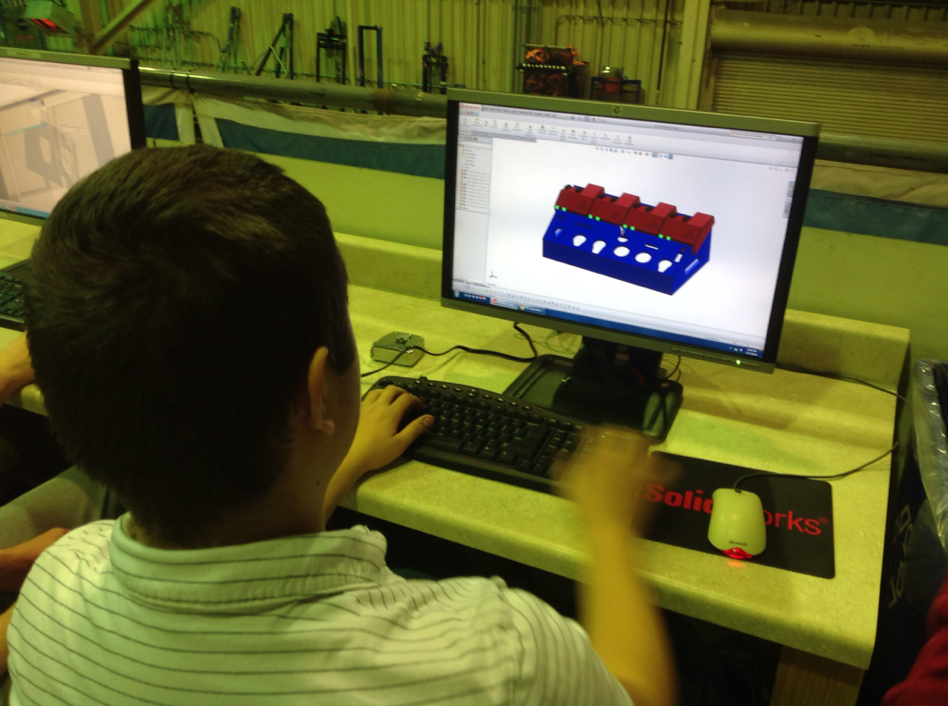
Today, the CAD team worked on the ball lifter assembly and piston positioning for the 2 position hood. We also went through the drive gearbox CAD to ensure everything is in ship shape before manufacturing begins.
The team also worked to finish up the 3D model of the cordless drill holder, finalizing the hole placement and overall ascetics. Once approved, the CAD model can be sent to Good Plastics to have it routed.
Additionally, others started work on the control board CAD, starting with the process of designing the control board plates itself. They also found and selected all the screws for the control board. Next, the control board’s button layouts will need to be designed and modeled.
Award Submissions
The drafting of the Chairman’s Award Essay thesis began today. Team members brainstormed and wrote tentative theses in preparation for outlining over the weekend. Additionally, they also reviewed previous submissions for the Chairman’s Award and discussed the implicit intent of the thesis. They decided that the underlying message of the essay should emphasize the development of the team since its 2004 Chairman’s Award victory and how the team has continued to set a new direction since then. The team also plans to portray how it has further emphasized outreach and how inspired others in our local community and abroad.
Manufacturing
Today was a slow day on the manufacturing front. The primary task of the day was shortening the drive gearbox piston spider standoffs.
Pit shelving
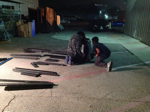
Today, students worked on organizing the pit storage shelves. Prior to today’s work, the shelf storage had been bound by tape, but now, the tape has been replaced with Velcro straps and certain beams were marked to point to the holes used in assembly. This will help save time during pit set up and tear down and prevent us from having to keep reusing expensive tape to simply bundle the segments together.
Action Items
- Check the Trello!
- Test and improve intake and shooting mechanisms on the robot prototype
- Finalize and approve the model of the cordless drill holder to be sent to Good Plastics
- Look through the website and all its pages and condense into a Google Doc a list of everything outdated, inaccurate, or otherwise unfit for the website.
- Organize outside storage area to make obtaining materials faster, simpler, and safer.
Day 13: Intake Construction, Flywheel Prototype, CAD
by Jeffrey Kaufmann
Flywheel Prototype
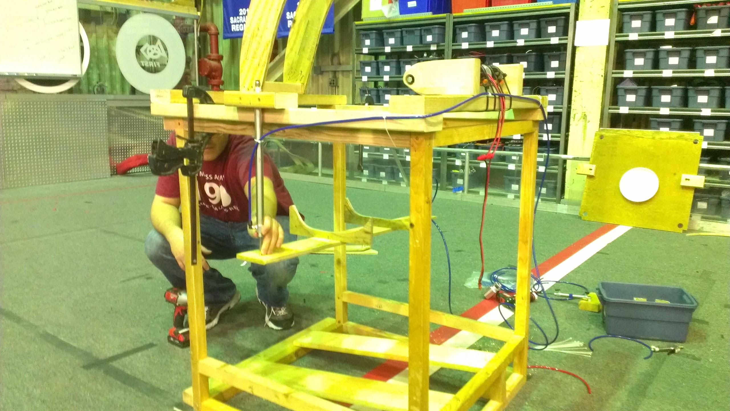
Today, work continued on the automated ball loading mechanism for the flywheel prototype. This “popper” will use two pneumatic pistons to quickly and precisely load balls into the shooter for more consistent and realistic testing. Tomorrow, the entire shooter will be mounted on top of the robot drive base along with the intake and to test the integration of the three systems.
Intake Construction
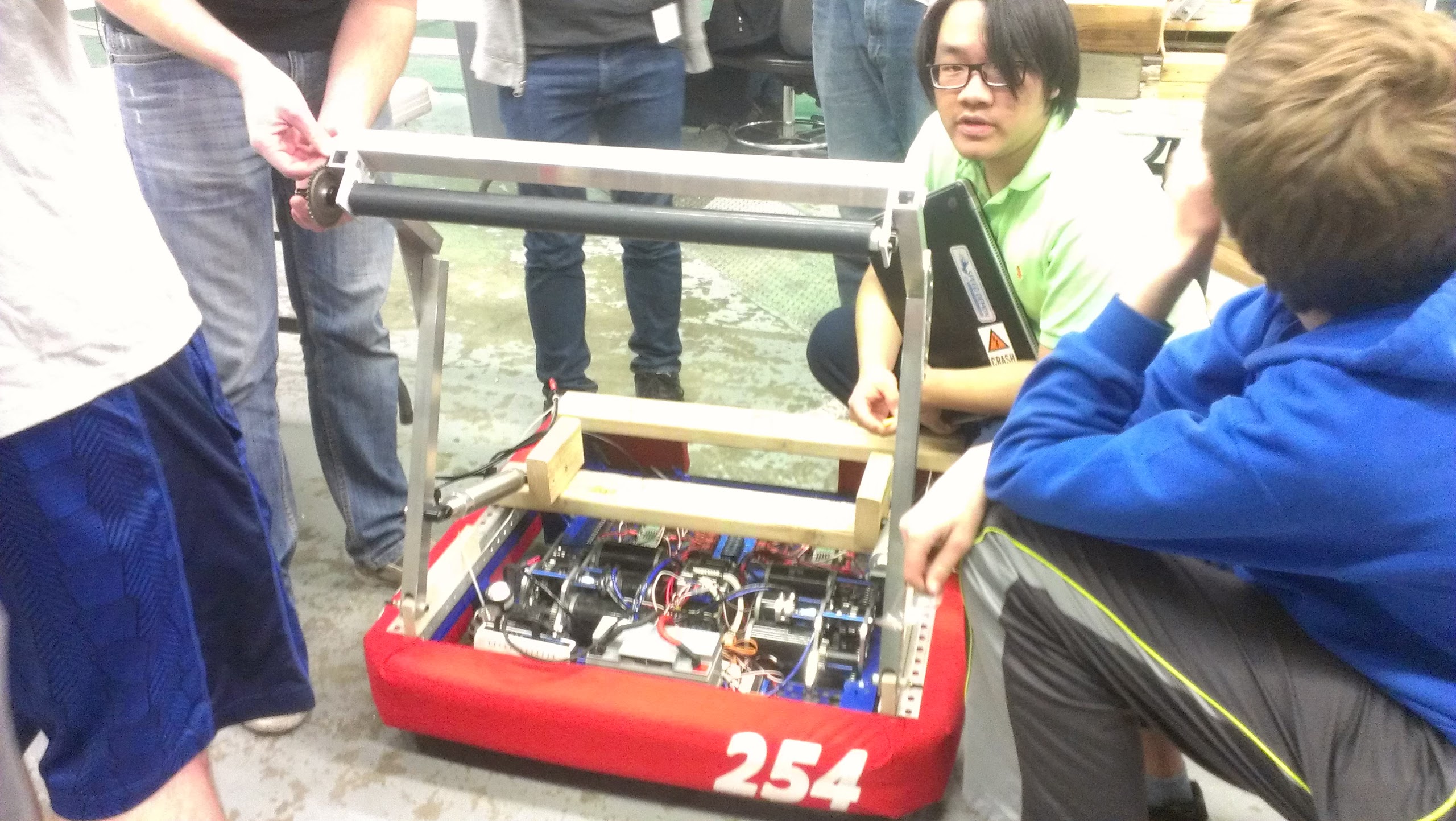
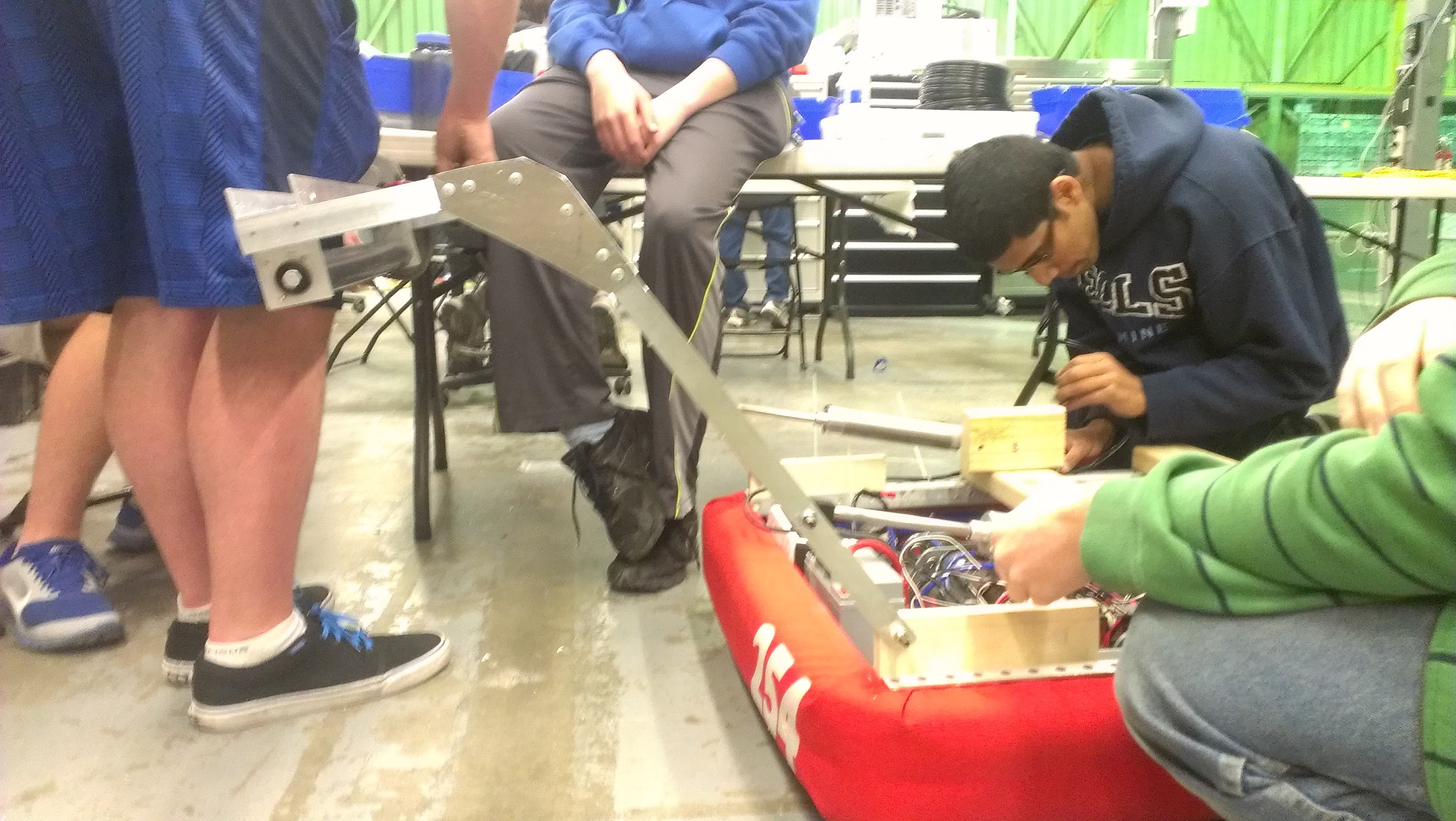
Other team members worked on creating a new prototype intake. This intake was created to the dimensions currently in place in the robot CAD model. It will be able to flip down with two pistons. The intake will utilize one mini CIM motor to drive the roller. When the intake is down, it can suck a ball and pull it up against the bumper. When the intake comes up while holding a ball, it pulls the ball into the robot. This will later be integrated with the shooter and “popper.”
Later in the night, the intake was finished and tested with the robot driving around. While this test did not utilize pneumatics, it did show that the intake successfully could pick up balls both while stationary and moving.
CAD
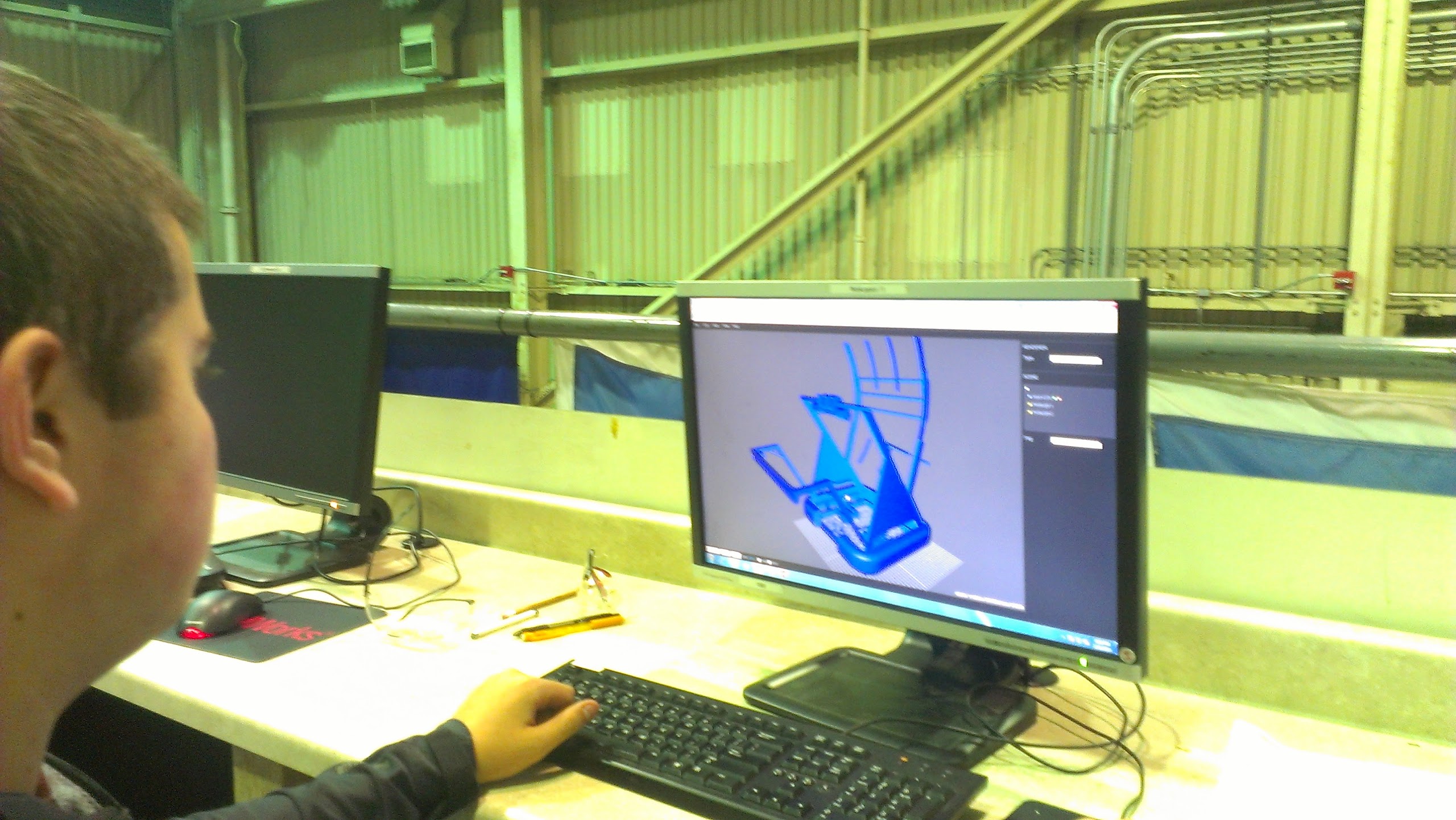
We also worked to create 3D render of the robot that can be used for the touch screens in the pit. Specifically, we worked to convert the current CAD model of the robot into a website that can be manipulated on a touch screen. This will be a fun, interactive way for visitors and judges to explore the CAD model of our robot.
In addition, we continued work on the Cordless Drill Holder. Some students were finishing up the CAD upstairs and figuring out the final dimensions so the organization unit can fit in one of our travel crates. Others were using the drill press and mill to make precise prototype holes in wood for the drill chucks to fit in. These test pieces were then used to get accurate dimensions in the CAD that will be later sent to Good Plastics to be professionally routed in blue HDPE plastic.
Action Items
- See the Trello boards!
- Continue work on Intake construction
- Keep testing 3-D render
- Finish Flywheel Shooter Prototype and integrate with Intake prototype and Overkill drive base
- Finish CAD of Cordless Drill holder
Day 12.5 – Testing the Lidar
Today, the team tested an advanced Lidar Sensor solution. Extensive testing was performed (approx 30 min).
Day 12: Design Review and Further Prototyping
by Dan Ngo ’17
Design Review
The highlight of the day was the design review, during which the team congregated to discuss and possibly finalize the strategy and conceptual robot design thus far. The team decided that its overall strategy would be aimed at being able to first self score all three balls in autonomous. This removes any risk of relying on teammates during this valuable portion of the match. Subsequently, in teleoperated mode, general scoring would be prioritized. Assisting, while useful for qualification points, will likely only become significant in elimination matches.
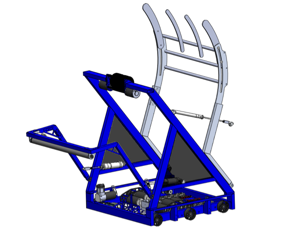
Regardless of strategy, we agreed that the robot should be able to perform all the tasks in the game (shooting, passing, catching, etc.). We determined that a flywheel shooter aligns with these goals and packages nicely in the robot’s envelope. Additionally, to be able to score all three balls in autonomous, the team would first need a mechanism to hold and feed them into the shooter. This is currently being prototyped.
Programming
Team members continued work on integration of the ultrasonic sensor. We also worked on making programs to remotely access feedback from the robot, to ease autonomous testing. We also installed new, smaller, joysticks on the control board. These joysticks use hall effect sensors instead of potentiometers for more reliable and precise control.
Manufacturing
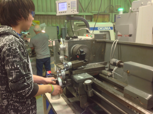
Today, groups worked on machining parts for the gearbox, the ongoing arm prototype, and started the feeding mechanism prototype.
Action Items
- Continue intake prototype
- More testing and coding
- Work on the feeding mechanism prototype
Day 11: Prototyping, Design, CAD, and Testing
by Trevor Salom ’17
Programming
Today, the programmers worked on testing a VEX ultrasonic sensor to see whether the robot could use it to gauge its distance from the wall of the field. The VEX sensor was used as a temporary stand-in while the programming team awaits the arrival of the competition sensors.
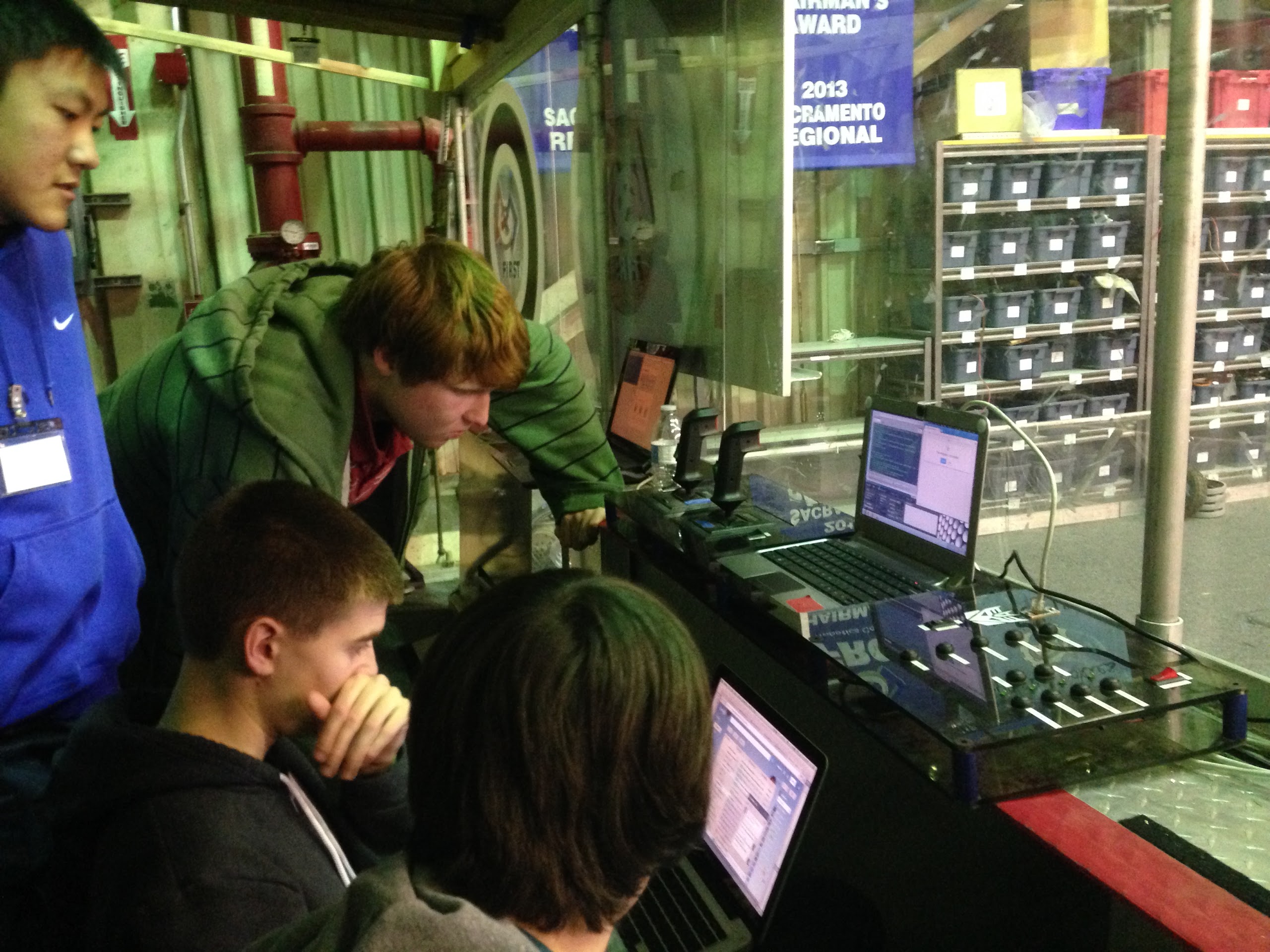
In addition, they continued working on applications to graph the feedback sent by the robot.
Design
Today, we continued the design of the robot and continued detailing the main intake, the shooter wheel and the actuating hood. The shooter is powered by two mini CIM motors with power transmission through small GT2 timing belts. The front intake has a 550 motor mounted on the end of the arm with a two-stage belt reduction aimed to give a roller surface speed around 15 ft/sec. This speed was determined by estimating the average robot speed while intaking (10 ft/s) and determining the amount of time we hope for an intake to take.
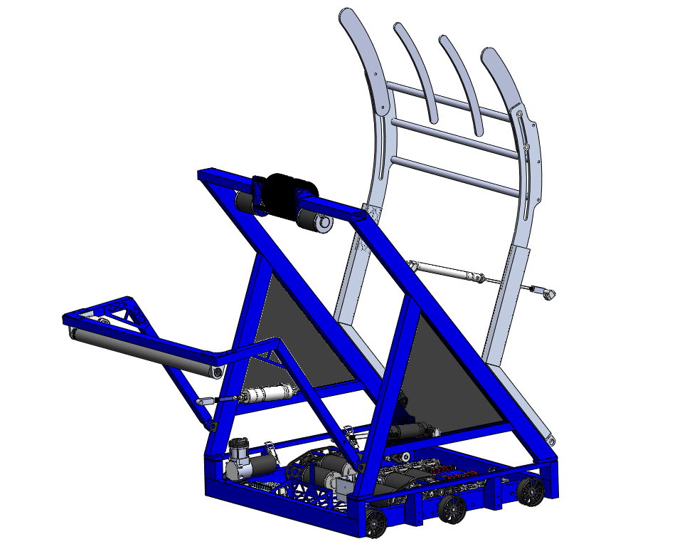
Furthermore, we finalized the design of the baseplate and continued work on the design of a drill holder.
Manufacturing
Today, we began making the outer bearing housings. A large order of material arrived today from our aluminum supplier. The aluminum plate for the robot bellypan was dropped off at sponsor BAE systems for waterjet cutting. We expect the baseplate to be cut on Monday.
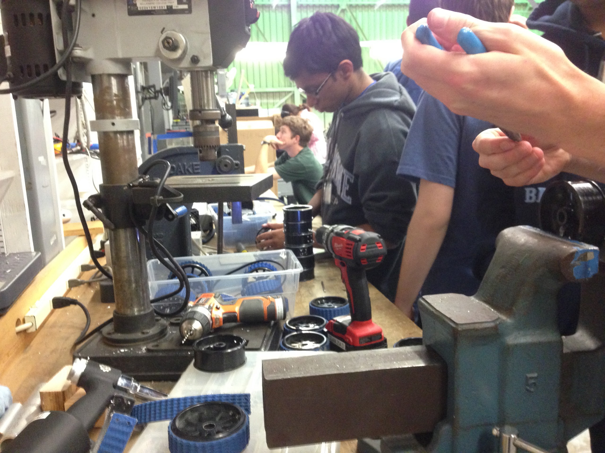
Furthermore, a number of team members cut tread today. This tread will be used on practice wheels for existing robots and may eventually be placed on the competition robot (once its wheels are made).
Roller Intake Prototype
Work was also started on building a more refined version of the roller intake prototype. The intake will be raised and lowered by pistons, and will be based on a CAD drawing of the final design.
Action Items
- Finalize Robot Design and CAD under Andrew Torrance and Mani Gnanasivam
- Refine Intake Prototype under Dan Judnick
- Programming and related testing with Brandon or Stephen
- Help out the Media Team under Kevin or Maxwell
- Ask a leader or mentor or request access following the instructions on the whiteboard to see what other tasks are listed on the Trello.
Day 10: Rest Day
In honor of our first day of rest of the season, here’s a GIF of the season’s latest dance craze.
Today, we didn’t meet at the lab. Some team members worked on CAD on their own.
