FRC Day 16 Build Blog
Day 16: Zipper Hopper and Intake
Prototyping
Zipper Hopper
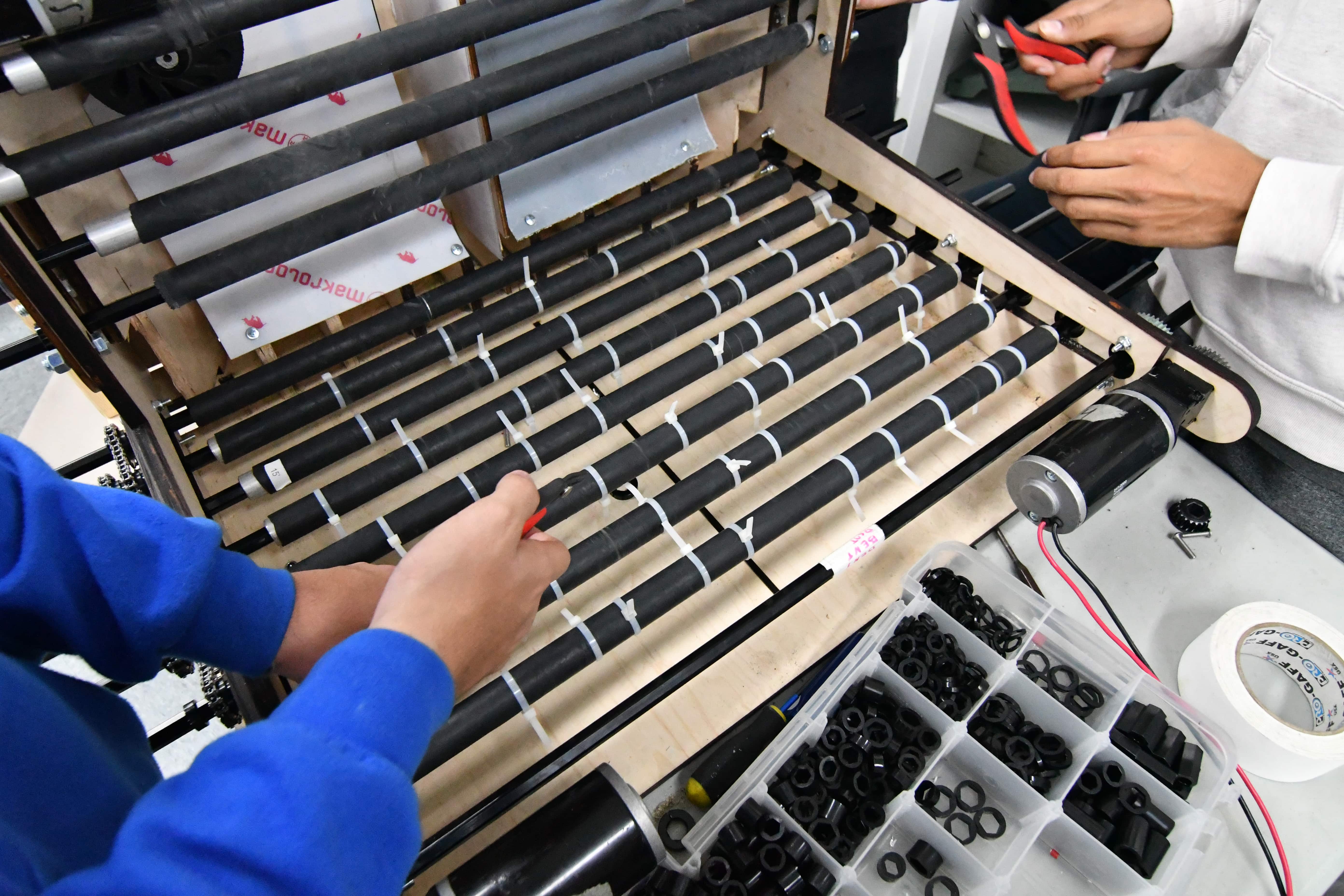
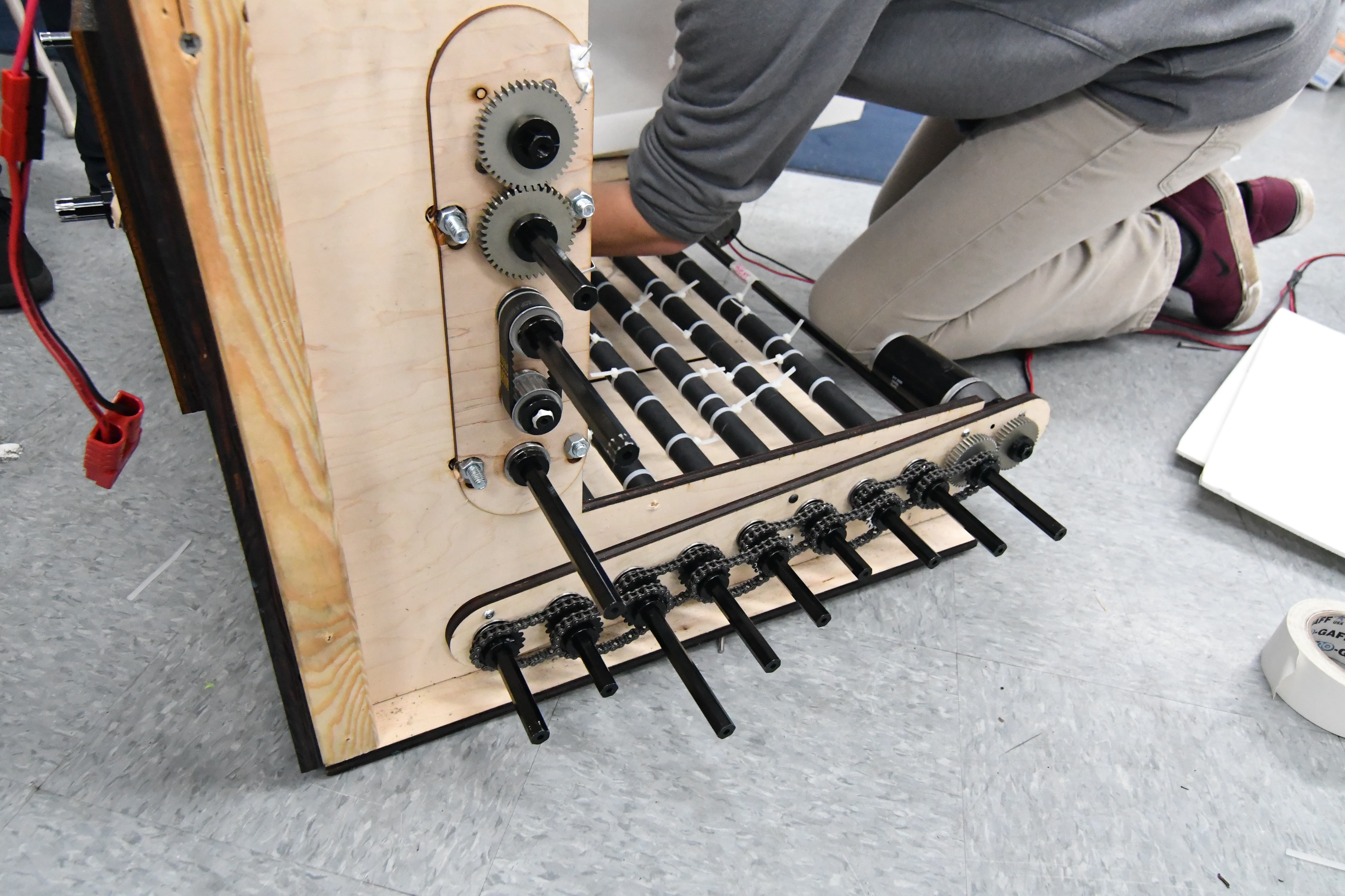
Today we solved the problems of the previous designs by removing the polycord and replacing it with chain. While disassembling the prototype, we found another link of the polycord which melted onto the delrin hub, so in the future we’ll definitely avoid using polycord in this type of situation. The chain increased efficiency so much, that we actually ran into problems with our feeder roller. As a result, we found that it needed a second CIM to drive it efficiently without burning out. After testing it, we decided to iterate on the zipper wheels themselves. Changing from an active to passive solution, we changed one side to metal wheels with little traction. Specifically, our intake wheels from 2015, without any polyurethane. On the other side, we added a second mounting hole and added two chain run rollers. We found that this worked well,and we need to continue to iterate and finalize the hopper design.


Intake
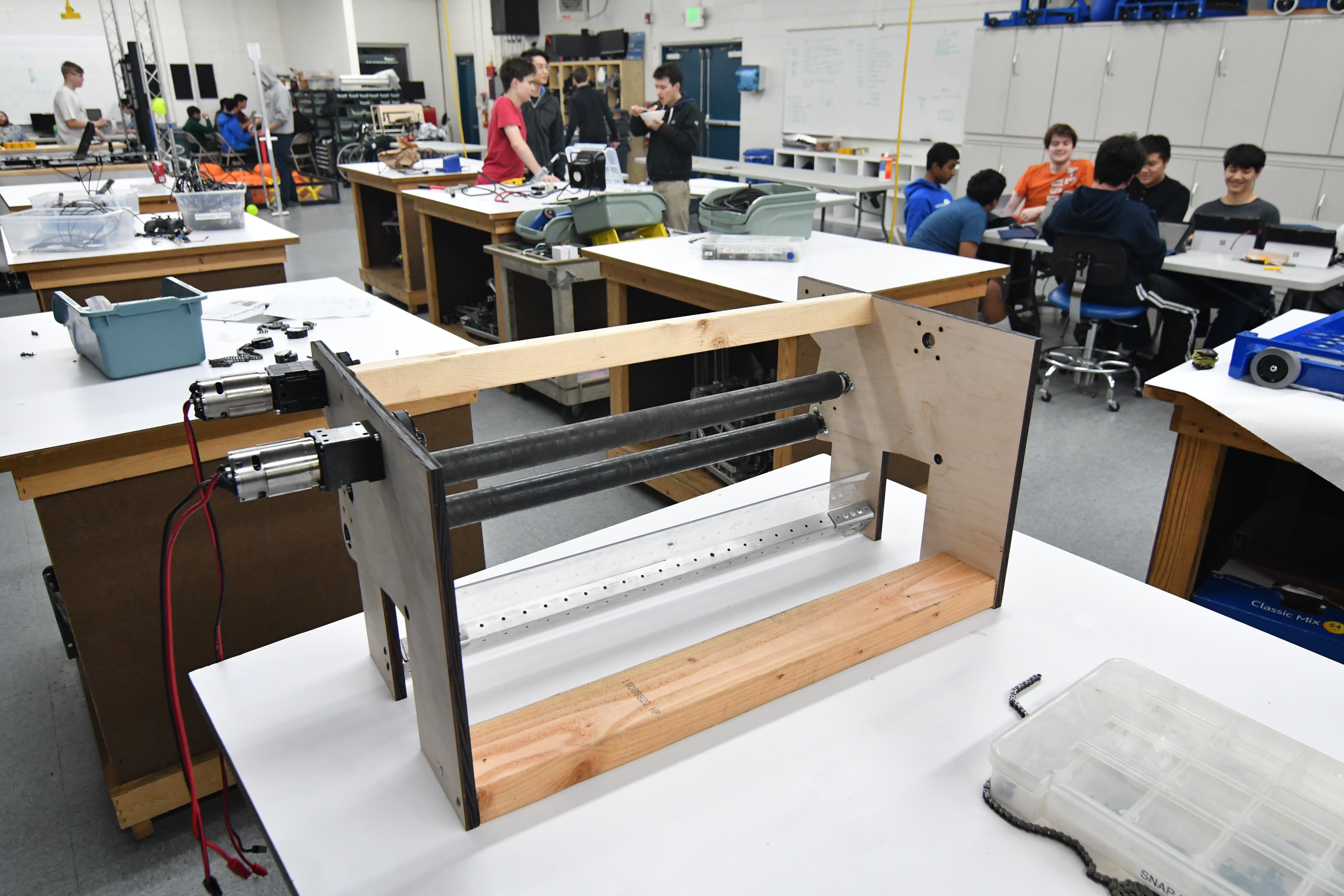
Today for the intake we worked on the side plates and made the geometry match that of the currently-functional prototype. We tried to make them look good and then we pocketed them.
We chose a piston and have a preliminary extra plate that mounts via small brackets to the 3/16" bolts in the drivebase bumper-support tubes. We had to change the motor mount plates so the standoffs would avoid hitting the many paths of belts.
We still need to finalize the packaging of the intake into the overall superstructure and integrate it with the hopper and feeder.
We also need to figure out how to get the polycarbonate ramp to deploy because currently it doesn't fit within the starting configuration when the intake is raised.

.png)
.png)
Programming
Computer Vision
Today we began work on modifying the Android vision tracking app, used in last year’s challenge to aim at the goal, for the boiler target. The underlying thresholding code, which isolates the illuminated (green) retroreflective tape from the rest of the image, will remain the same, but the processing code will need to be changed.
We use OpenCV, the de facto open-source computer vision library. We began with a thresholded picture of the goal that shows only the retroreflective tape on the target. Then, we created a contour, or an outline of the “area of interest.” We initially experimented with this using GRIP, an application that allows one to interact with OpenCV using easy drag-and-drop blocks, but we quickly realized GRIP’s limitations. We then moved to Python for prototyping purposes, and we were able to draw an outline of the contours.
Finally, we also discussed using the pinhole camera model to determine the robot’s distance from from the goal, which determines how fast/hard we launch the ball (Wikipedia Article). Given the actual object height (in inches/cm), the camera’s focal distance (in pixels), and the height of the object in the camera (in pixels), we’re able to calculate the distance from the object. The exact means by which we implement this are to be determined.
If you’d like to help with computer vision, please set up OpenCV for Python (64 bit!) using these instructions.
Thresholded image:
Thresholded, with contours highlighted in green (by the OpenCV program):
Autonomous Code
Today we worked on cleaning up and documenting the autonomous pathing code. As part of the cleanup process, we reworked the pathing code's coordinate system. The old coordinate system was a left handed system, with positive x values to the right and positive y values moving downwards. This placed the origin at the top left hand corner of the field. However, angles still moved counterclockwise, making the whole system convoluted and confusing. The new coordinate system we implemented today is much more straightforward. Positive x is right and positive y is up, while angles increase as they move counterclockwise. This new system makes trigonometric functions far easier to use, as with the old one we would always have to invert any y values.


